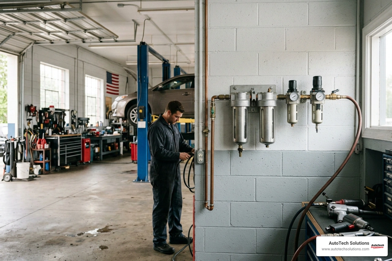
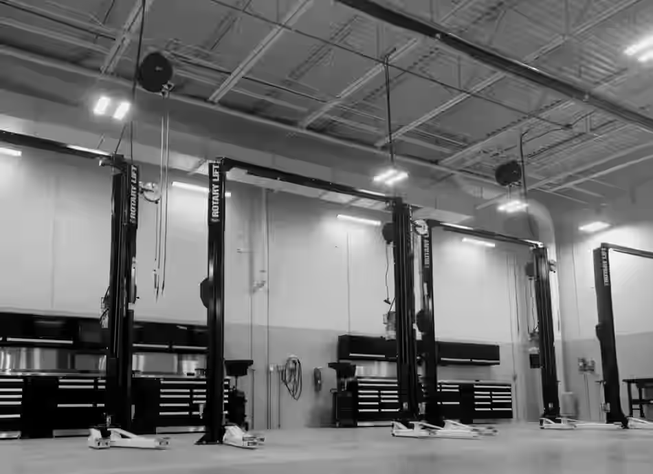
Why Every Automotive Shop Needs to Understand Compressed Air Ring Mains
A compressed air ring main is the backbone of any high-performing automotive service facility — and getting the design right can be the difference between consistent tool performance and costly, frustrating pressure drops throughout your shop floor.
Quick answer: What is a compressed air ring main?
- A closed-loop piping layout that connects back to its starting point, forming a complete circuit around your facility
- Air can travel to any outlet from two directions simultaneously, equalizing pressure across all drop points
- Unlike a straight-line (radial) system, pressure stays consistent even when multiple technicians are using air tools at the same time
- It is the preferred distribution method for commercial automotive shops, collision centers, and industrial facilities with multiple points of use
For shop managers, the stakes are straightforward. When pressure drops mid-task — a paint gun sputtering, an impact wrench losing torque — productivity stops and frustration starts. Traditional straight-line piping systems struggle to keep up when demand spikes across multiple bays. The ring main design solves this at the infrastructure level, before the problem ever reaches your technicians.
The good news is that understanding how a ring main works, what materials to use, and how to size it correctly for your facility is more accessible than most shop owners expect.

What is a Compressed Air Ring Main?
To truly appreciate the value of a compressed air ring main, it helps to compare it directly to traditional piping configurations. In many older or rapidly expanding commercial shops, air distribution is built using a radial layout or straight-line piping.
In a straight-line system, a single main header pipe runs from the compressor receiver tank down the length of the workshop, with individual drop lines branching off to each service bay. The primary limitation here is simple physics: the air has only one path to take. As air travels further down the line, friction against the pipe walls slows it down, causing a progressive drop in pressure. If a technician at the very end of the line attempts to run a high-demand tool while other bays are active, they will experience a severe performance drop.
By contrast, a compressed air ring main uses a closed-loop layout. The piping forms a continuous loop around the perimeter of the workshop, starting at the compressor discharge point and terminating back at the same location. This structural difference completely changes how air behaves.
When a tool is activated at any drop point along the loop, compressed air flows from both directions of the ring to feed that specific outlet. This effectively doubles the cross-sectional area of the delivery path, dramatically reducing flow resistance and stabilizing pressure. Whether you are running multiple heavy-duty impact guns or operating high-demand paint booths in a collision center, the closed-loop design ensures that flow is balanced dynamically across the entire facility.
For a deeper dive into how different piping layouts affect overall performance, check out our guide on straight-line vs ring main comparison. Getting this layout right from day one is a core component of a professional air compressor installation that protects your investment in high-end pneumatic tools.
The Physics of Pressure: How Ring Mains Eliminate Pressure Drops
In any commercial air system, pressure drop is the enemy of efficiency. Every bend, coupling, and foot of pipe introduces friction loss, which resists the movement of compressed air. As flow velocity increases to meet high air demand, this friction loss climbs exponentially.
In a straight-line layout, the pressure drop at the furthest tool is cumulative. To compensate, many shops resort to over-pressurizing their entire system at the compressor. However, this is an incredibly expensive workaround. A well-made compressed air piping system should incur a pressure loss of less than 10 percent of the air compressor's discharge pressure. Ideally, the target should be to make sure the pressure drop in the pipes does not exceed 0.3 bar between the air compressor discharge point and the furthest point of consumption.
When you implement a closed-loop ring main, you drastically reduce flow velocity through any single section of pipe because the air is split into two paths. Lower velocity means significantly less friction, which translates to a highly stable system pressure.
| Performance Metric | Straight-Line (Radial) Piping | Closed-Loop Ring Main |
|---|---|---|
| Air Flow Direction | Single path only | Dual-directional flow |
| Pressure Drop at Furthest Point | High (often exceeding 1.0 bar under load) | Minimal (easily maintained under 0.3 bar) |
| Friction Loss | Cumulative along the entire run | Distributed and minimized |
| System Efficiency | Low (requires higher compressor discharge pressure) | High (allows lower compressor discharge pressure) |
| Simultaneous Tool Performance | Inconsistent; drops when multiple bays are active | Consistent across all drop points |
By maintaining a stable pressure throughout the loop, you can lower the discharge pressure setting on your compressor. This has a massive impact on your bottom line: a 1 bar reduction in discharge pressure requirements can equate to a 6-10% reduction in energy consumption. Over a year of heavy commercial operation, this structural adjustment yields substantial savings on your utility bills.
To understand how optimizing your layout contributes to long-term operational health, read more about why a ring main design is beneficial for commercial facilities.
Material Selection for Your Compressed Air Ring Main

Selecting the right piping materials is just as critical as choosing the correct layout. The material you choose dictates the system's air quality, leak resistance, installation labor costs, and overall system longevity.
Historically, commercial shops relied on black iron or galvanized steel. While durable, these traditional materials are heavy, difficult to install, and highly prone to internal corrosion over time. Rust and scale flake off from the inside of the pipe, clogging filters, destroying tool seals, and ruining paint finishes. Today, modern materials offer far better performance and lower total cost of ownership.
Aluminum Piping: The Gold Standard for Modern Shops
For professional automotive facilities, aluminum has quickly become the industry standard. Aluminum piping is lightweight, exceptionally strong, and completely resistant to corrosion. This ensures that the air delivered to your tools remains clean and free of particulate matter.
One of the greatest advantages of aluminum is its incredibly smooth bore. Because the inner walls of the pipe have virtually no roughness, friction loss is minimized, allowing air to flow with maximum efficiency. Furthermore, modern aluminum systems utilize specialized, leak-proof connections that prevent the slow, costly air leaks common in threaded steel systems.
Investing in high-quality aluminum piping solutions ensures that your shop enjoys optimal flow rates and zero risk of internal pipe degradation.
Copper, Steel, and Plastic Options in a Compressed Air Ring Main
While aluminum is the premier choice, other materials are frequently considered depending on budget and specific application needs:
- Copper: Highly durable and corrosion-resistant, copper provides an exceptionally clean air path. Its thermal conductivity also helps cool the air, allowing moisture to condense out of the stream before it reaches tools. However, copper requires skilled labor for soldering or pressing, making installation expensive.
- Galvanized Steel: Strong and resistant to physical damage, steel is still used in heavy industrial settings. However, threading steel pipes is labor-intensive, and the zinc coating will eventually degrade, leading to corrosion.
- MDPE (Medium-Density Polyethylene) & Nylon: Specialized engineering plastics are increasingly popular for modular systems. They are lightweight, completely corrosion-proof, and highly flexible.
- Push-Fit Fittings: Modern plastic and soft-metal systems often utilize advanced push-fit fittings. These components are so user-friendly that they can reduce installation time by up to 50% compared to traditional threading or soldering. They also make future shop reconfigurations incredibly simple.
For more details on keeping your system leak-free and selecting components that resist wear, consult our air compressor preventative maintenance guide.
Designing Take-Off Points and Drops for Moisture Control
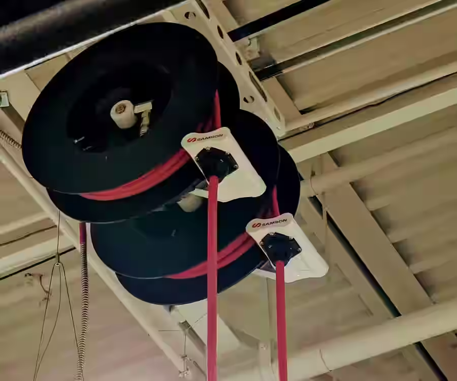
No matter how dry the climate is in your region, compressing air naturally concentrates moisture. If this water is allowed to travel down your piping and enter your tools, it will wash away lubricating oils, corrode internal components, and ruin paint finishes. Proper condensate management is a non-negotiable aspect of professional system design.
Preventing Water Contamination in a Compressed Air Ring Main
To keep water out of your expensive equipment, the physical drops (take-off points) must be designed to naturally isolate moisture.
- Swan Necks (Goosenecks): Never pull air directly from the bottom of the main loop. Instead, take-off points should exit from the top of the main horizontal pipe, curving upward and over in a "swan neck" shape before dropping down to the workspace. Since water is heavier than air, gravity keeps the liquid condensate at the bottom of the main loop, allowing only dry air to enter the drop line.
- Drop Legs: Extend the vertical drop pipe past your primary quick-disconnect outlet. This extension, known as a drop leg or dirt leg, acts as a collection point for any moisture that does manage to enter the drop. A drain valve (either manual or automatic) should be installed at the very bottom of this leg to allow regular draining of accumulated water.
- Filtration and Water Traps: Install high-efficiency particulate filters and water separators immediately before your air drops and at key points along the loop.
To ensure your team is staying on top of water management and system checks, review our comprehensive air compressor preventative maintenance guide.
Sizing and Planning Your Commercial Workshop Piping Layout
Properly sizing your compressed air ring main requires a clear understanding of your shop's current air demand and your plans for future expansion. If the pipe diameter is too small, flow velocity will be too high, resulting in severe pressure drops regardless of the loop layout. Conversely, oversized pipes increase initial installation costs, though they do provide beneficial extra storage capacity.
When planning your layout, consider the following key factors:
- CFM Requirements: Calculate the total cubic feet per minute (CFM) required if all primary tools in your shop were running simultaneously. Always size your main loop based on this peak load, plus a safety margin of 20-30% for future growth.
- Loop Length: The longer the total run of your ring main, the larger the pipe diameter needs to be to keep friction losses below the recommended 0.3 bar threshold.
- Isolation Valves: Strategically place ball valves around your ring main. This allows you to isolate specific sections of the shop for maintenance or expansion without shutting down the entire air supply, keeping the rest of your service bays fully operational.
For detailed planning support tailored to commercial automotive shops in Michigan and the Carolinas, see our air compressor installation guide Michigan.
Frequently Asked Questions about Compressed Air Ring Mains
Is a ring main system suitable for small automotive workshops?
Yes. While ring mains are highly praised in massive multi-bay facilities, even a smaller shop with three to four bays benefits from a closed-loop system. It ensures that when one technician uses a high-draw tool, it doesn't starve the adjacent technician's air supply.
How does a ring main design improve energy efficiency?
By allowing air to travel through two paths to any given outlet, the ring main reduces flow velocity and friction. This minimizes pressure drop, meaning your air compressor does not have to work as hard or run at a higher discharge pressure to deliver the required pressure at the tool.
What is the maximum pressure drop allowed in a professional air system?
In a professional commercial setup, the total pressure drop between the compressor discharge point and the furthest tool should never exceed 10% of the system pressure, with a target of keeping it under 0.3 bar for maximum efficiency.
Conclusion
A properly designed compressed air ring main is one of the smartest infrastructure investments an automotive service shop can make. By eliminating pressure drops, protecting tools from moisture, and dramatically lowering energy costs, a closed-loop system pays for itself over years of reliable service.
At AutoTech Solutions, we specialize in designing and installing robust, commercial-grade shop infrastructure. From professional car lift installation and advanced exhaust extraction to optimized compressed air networks, we help shops across Michigan, North Carolina, and South Carolina maximize their uptime and efficiency.
Ready to upgrade your workshop's air distribution? Schedule your professional air compressor installation for automotive shops with AutoTech Solutions today, and let our expert team build a system tailored to your business needs.