
Smart Industrial Machine Installation Starts With a Controlled Plan
Industrial machine installation should follow a controlled sequence: verify the site and utilities, inspect and stage deliveries, rig equipment into place, level and anchor it, complete tie-ins, then test each system before production use. For commercial automotive shops, this applies to professional car lift installation, alignment systems, tire service equipment, air compressors, exhaust extraction, and other fixed shop infrastructure.
The goal is simple: avoid unplanned downtime, safety gaps, and costly rework. A machine is not truly installed when it reaches its marked floor location. It must be supported by the right slab, connected to suitable power and air, protected by safety systems, and proven under operating conditions.
A strong installation plan assigns clear owners for rigging, mechanical setup, electrical work, utility connections, controls, and final acceptance. It also keeps temporary hoses, wiring, shims, and access routes from becoming permanent shortcuts.
AutoTech Solutions Staff will walk through the practical steps that help modern facilities install professional shop equipment safely, accurately, and with long-term reliability in mind.
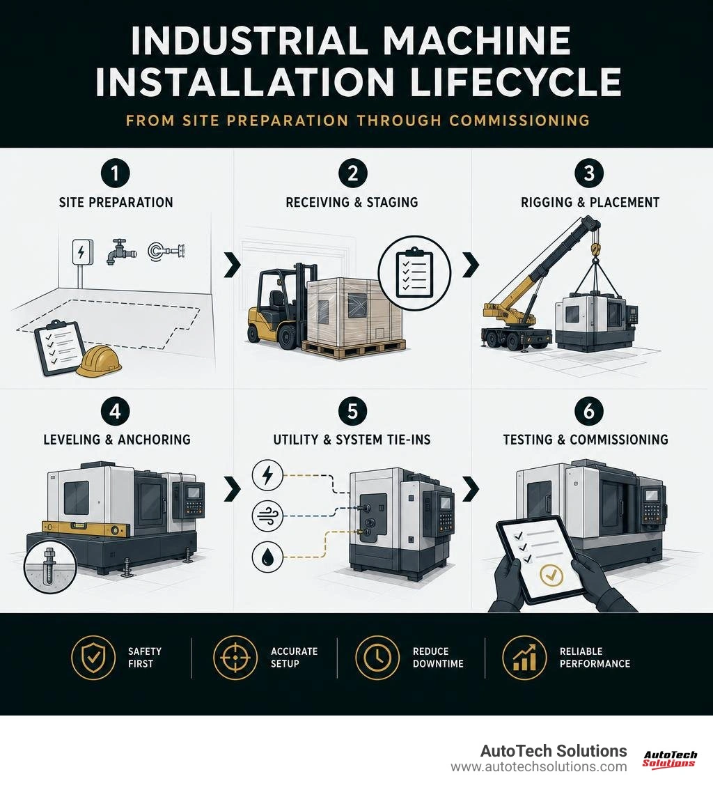
Industrial machine installation word roundup:
Pre-Installation Engineering and Site Preparation
Flawless machinery deployment begins long before the transport carrier backs up to your facility bay. Comprehensive facility buildout equipment planning guarantees that your building's civil and structural envelope can withstand dynamic operational stresses. Heavy industrial machines create both static dead loads and severe dynamic rotational and vibrational forces that transmit directly into the foundation.
Civil readiness requires evaluating structural floor loading, sub-base compaction, point-load distribution, and overhead clearances. Modern multi-axis machining cells and commercial vehicle service systems place massive concentrated loads across compact footprints. A continuous concrete foundation poured directly on grade with a 28-day curing cycle is mandatory to reach specified compressive limits.
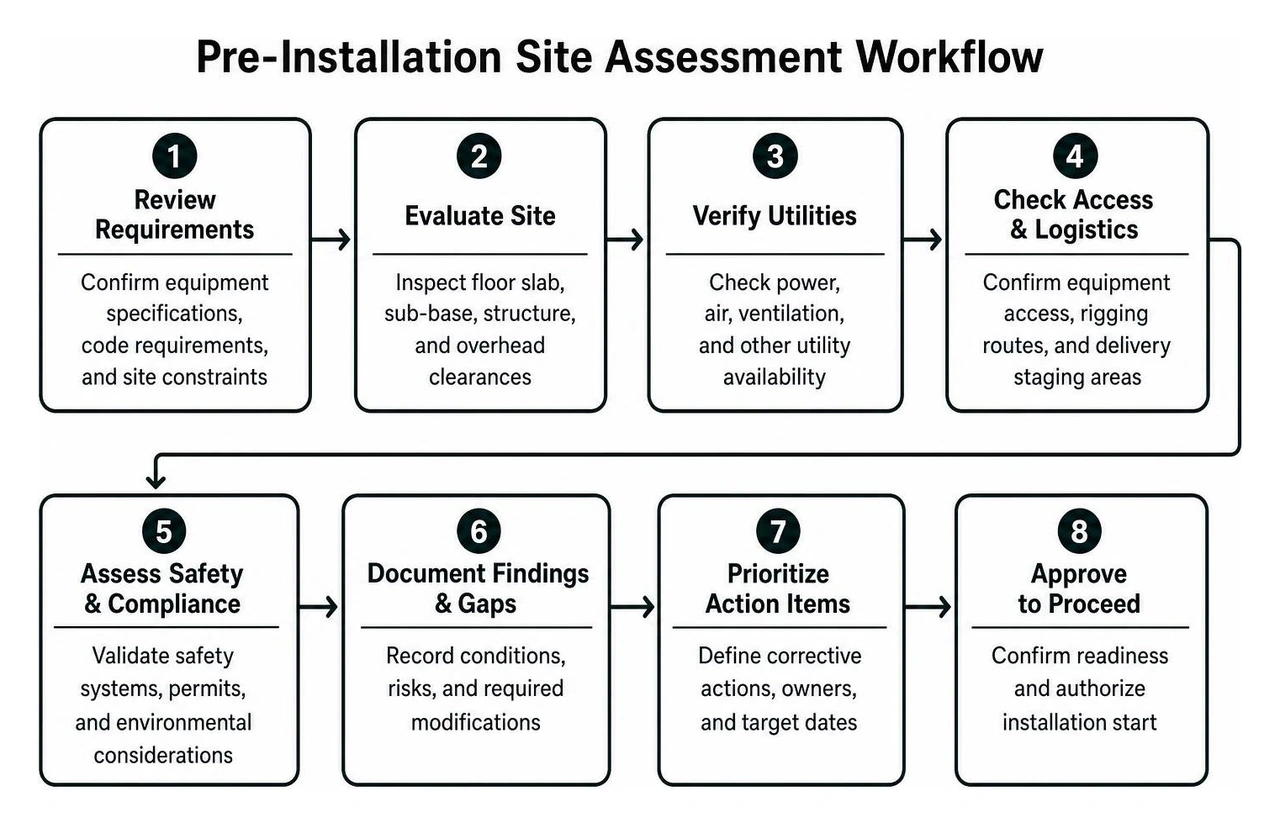
The following engineering standards reflect typical baseline requirements across commercial machine classifications:
| Equipment Category | Minimum Foundation Depth | Compressive Strength (28-Day Cure) | Anchor Torque Spec | Edge & Seam Clearances |
|---|---|---|---|---|
| Commercial 2-Post Automotive Lift (9,000 lb) | 4" (100 mm) | 3,000 PSI (207 bar) | 110 ft-lbs | 6" minimum from slab edge; 6.5" hole-to-hole |
| Standard Heavy Industrial Machine / Lathe | 6" (150 mm) | 3,500 PSI (240 bar) | Per OEM Bolt Spec | 12" minimum from slab edge or joints |
| Complex Multi-Axis Milling Center | 12" (300 mm) | 3,500 PSI (240 bar) | Re-check at 24 hrs | Continuous slab; no seams across bed |
| Industrial Palletizing / Articulating Robotics | ≥300 mm (C30 Grade) | ~4,350 PSI (30 MPa) | Chemical Anchor Spec | Leveled to ±1 mm/m; dynamic moment buffer |
Site Preparation for Industrial Machine Installation
Prior to equipment arrival, ground-penetrating radar (GPR) scans must detect embedded rebar, post-tensioned cables, and underground electrical or plumbing runs. Drilling an anchor hole directly into a structural rebar strand or hydronic heating line compromises structural integrity and brings projects to an immediate halt.
Engineers must establish primary floor datum points and laser layout lines across the installation footprint. When reviewing a manufacturer document like the VMT-750 Pre-install Guide, notice the strict prohibitions: machinery must never span expansion joints, cold seams, or slab stress cracks. If existing shop concrete fails compressive core testing or falls below the 3,000 to 3,500 PSI threshold, the target pad must be saw-cut, excavated, and repoured with reinforced 40 ksi rebar.
Cross-Disciplinary Team Coordination and Rigging Logistics
Industrial machinery placement demands clear coordination among multiple licensed trades. Millwrights, industrial electricians, piping fitters, and professional riggers cannot work in isolated silos without triggering physical spatial clashes on site.
Integrating these trades during commercial garage equipment planning ensures that electrical conduit drops do not conflict with overhead machinery clearance zones or structural framing channels. Rigging routes must be mapped out from the loading dock through interior access corridors. Verify door heights, overhead crane bridge clearances, structural floor capacities along the travel pathway, and forklift turning radiuses.
On delivery day, enforce the "one-voice" signaling rule during all rigging maneuvers. Only one designated, qualified signal person directs the crane or heavy forklift operator. When multiple workers shout conflicting directions in a live shop environment, near-misses and equipment damage occur.
Core Stages of Industrial Machine Installation
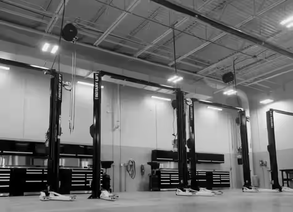
The moment equipment arrives at the receiving bay, quality control begins. Receiving technicians must inspect all crating, pallets, and shrink wrap for signs of transit trauma. As outlined in Plant Installation 101: What Happens From Delivery to Commissioning - Trudeau Meter, inspecting external shock indicators and tilt tags before signing the bill of lading protects the facility against hidden freight damage.
Photograph the equipment in the truck bed, inspect all tie-downs, and cross-reference the bill of materials against shipped accessory boxes. Uncrating must follow a strict parts-control protocol so leveling shims, mounting brackets, and hardware packs remain organized. Machinery should be offloaded using certified spreader bars or machinery skates, maintaining weight capacities with a 30% safety margin.
Precision Anchoring, Leveling, and Vibration Control
Positioning a multi-ton frame onto layout lines requires precision alignment techniques. Place master precision machinist levels (rated to 0.02 mm/m) across machined reference surfaces or machine beds. Shimming must utilize slotted, stainless steel horseshoe shims directly under base load points rather than stacking thin, unstable metal scraps.
Anchor holes must be drilled perpendicular to the slab using carbide bits, vacuumed clean of all concrete dust, and torqued using calibrated torque wrenches. For commercial vehicle lifts, tighten base anchors to the standard 110 ft-lbs specification. Non-shrink cementitious or epoxy grout is pumped under the baseplate to eliminate voids, absorb vibration, and distribute weight evenly. Remember the seasoned millwright adage: grout doesn't care about your deadline—it must fully cure before applying dynamic operating loads.
Eliminating "soft foot"—a condition where a mounting foot does not sit flat against the baseplate—prevents twisted machine frames and premature bearing failure. Use dial indicators to confirm foot deflection remains under 0.002 inches when loosening and tightening individual hold-down bolts.
Quality Control During Industrial Machine Installation
Our updated equipment installation guide 2026 highlights precision standards for rotating industrial drives. According to API 686 recommended practices, shafts between motors, gearboxes, and driven components must be laser-aligned within 0.001″ to 0.002″ of true collinearity.
Laser alignment compensates for thermal growth and distance between shaft ends (DBSE). When machines run up to operating temperature, metals expand; neglecting thermal growth calculations causes severe shaft deflection, seal failure, and high-frequency vibration during continuous operation.
Utility Integration and Infrastructure Hookups
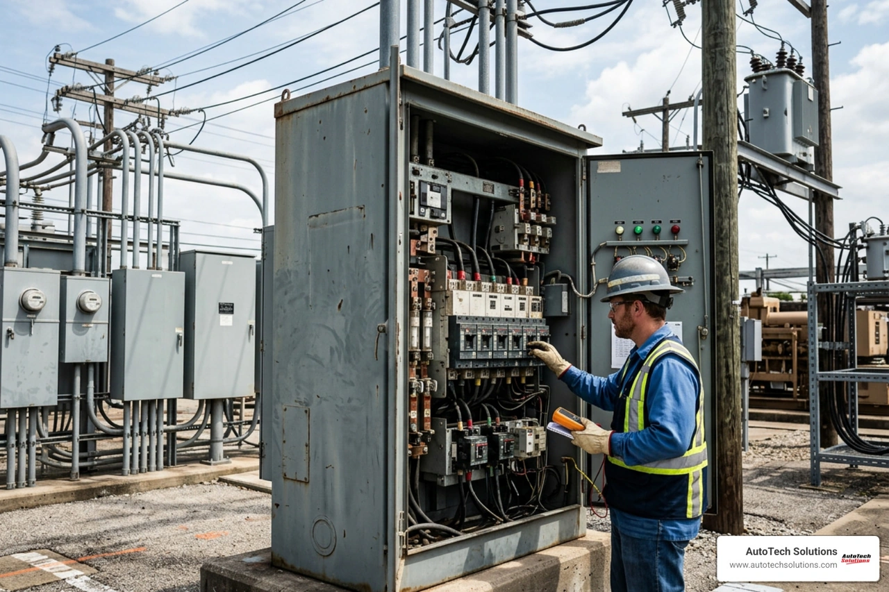
Connecting utilities is far more complex than running simple extension lines. Machinery reliability depends on stable, clean, and dedicated energy sources. Poor utility tie-ins represent the primary cause of intermittent control faults, emergency trips, and premature motor burnouts.
Proper industrial wiring installation requires dedicated chassis earth grounding with an electrical resistance under 4 ohms directly back to the main distribution panel. Running machine grounds through conduit, building structural steel, or water pipes is strictly prohibited. Three-phase incoming supply lines must be load-balanced within ±10% voltage variance across all legs to protect delicate drive electronics and computerized controllers.
Pneumatic, Hydraulic, and Exhaust Utility Drops
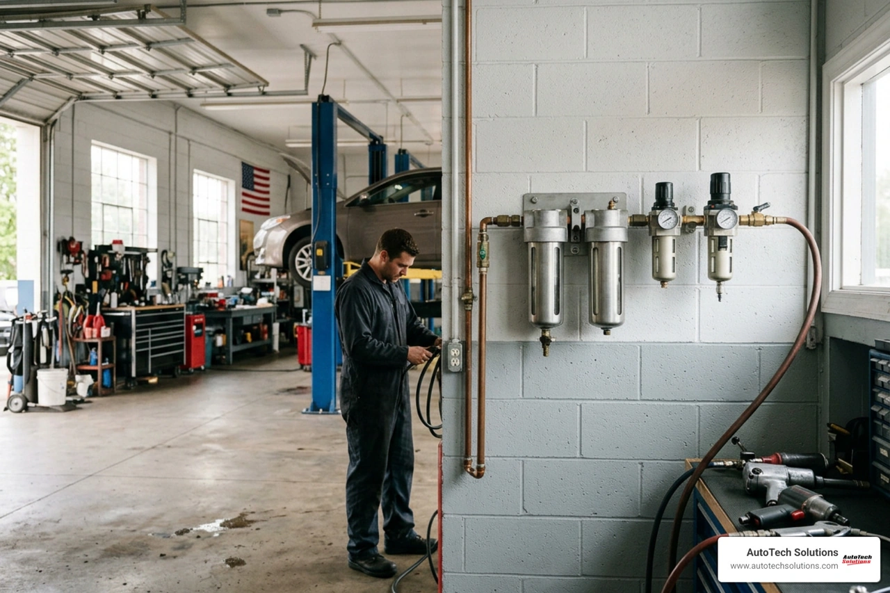
Industrial pneumatics must deliver consistent volume and dry air under full operating conditions. When completing an air compressor installation for automotive shop applications, line sizes must prevent pressure drops during peak simultaneous operations. Systems must incorporate refrigerated air dryers, particulate filters, and upstream pressure regulators if header pressure exceeds 120 PSI.
Commercial vehicle lifts and heavy hydraulic power units require clean fluid reservoirs filled with anti-wear fluids such as ISO AW32 non-foaming hydraulic oil. Hydraulic connections must be assembled without thread-tape contamination entering valving.
Furthermore, facilities running internal combustion engines or air-intensive shop equipment require dedicated, engineered exhaust extraction ductwork. Process piping connected to stationary machinery must be fully supported with independent pipe hangers to eliminate pipe strain, which otherwise pulls equipment out of alignment.
Electrical Distribution and Power-Up Sequencing
Safe electrical equipment installation mandates minimum physical clearances. Electrical control cabinets must maintain at least 3 feet (1 meter) of unhindered perimeter clearance for technician access and arc flash safety.
Technicians must execute a staged energization sequence:
- Lock out/tag out (LOTO) incoming main branch power.
- Confirm phase-to-phase and phase-to-ground isolation with a calibrated multimeter.
- Energize the main disconnect switch and verify incoming voltage stability.
- Power up secondary control transformers and verify 24V DC / 120V AC logic circuits.
- Close sub-breakers sequentially to power individual auxiliary modules (coolant pumps, exhaust extractors, hydraulic packs).
- Power main drive inverters and verify motor rotational direction during momentary jog tests.
Commissioning, Functional Testing, and Maintenance Handover
Physical placement and utility connections lead directly into dry-run commissioning. Technicians must perform mechanical pre-checks, ensuring all transit brackets, shipping locks, and protective coatings are completely removed before any axis rotates.
Initial testing involves a 30-minute no-load cycle. Technicians monitor PLC communications, sensor calibration, optical safety curtains, and temperature rise on bearings and motor casings. Establishing baseline vibration spectrum analysis during this run-in phase creates an engineering benchmark for future diagnostic monitoring.
Operational Acceptance and Safety Circuit Verification
Professional automotive equipment installation and service culminates in formal operational sign-off. Safety interlocks, emergency stop circuits, mechanical safety locking latches, and safety limit switches must undergo functional verification under loaded and unloaded states.
For automotive lifts, equalize carriage cables to within 1/4-inch side-to-side height tolerance. Run the lift through multiple full-stroke cycles to bleed trapped air from hydraulic cylinders. Technicians verify mechanical safety latches click in audible synchronization before raising full rated shop loads.
Preventive Maintenance Strategy and CMMS Integration
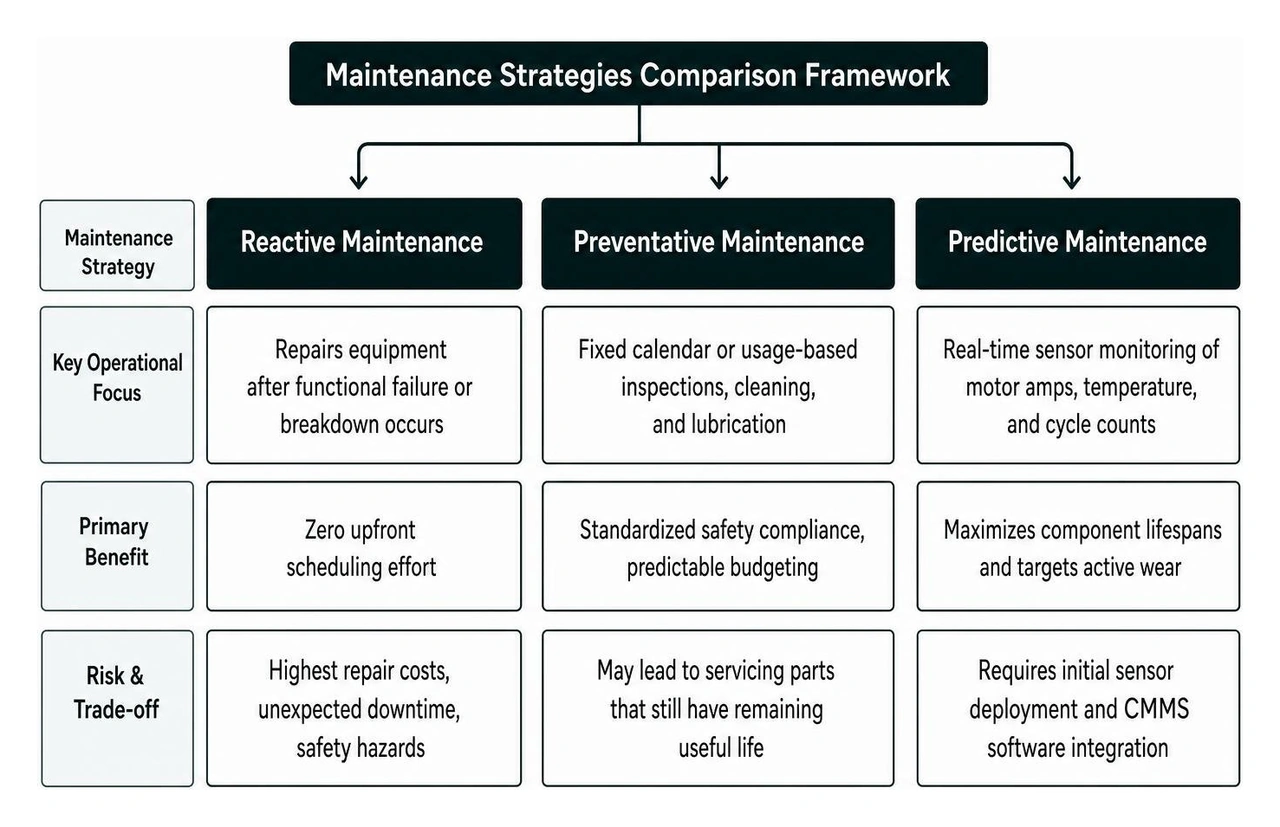
An installation remains incomplete until maintenance protocols are established. Reviewing an electrical preventative maintenance tips guide helps facility leads establish day-one lubrication logs, spindle fluid check cadences, and filter replacement schedules inside their Computerized Maintenance Management System (CMMS).
Planning for equipment uptime also involves understanding common wear factors that lead to industrial motor repair, such as unaddressed harmonic vibration, bearing contamination, or thermal overload. Handing over finalized as-built electrical schematics, spare parts lists (belts, seals, sensors), and standard operating procedure (SOP) documentation ensures shop technicians maintain equipment efficiency over decades of hard service.
Frequently Asked Questions About Industrial Machine Installation
What concrete foundation specifications are required before machine installation?
Commercial equipment foundations generally require a cured concrete slab with a compressive strength between 3,000 and 3,500 PSI (207 to 240 bar). Standard automotive service lifts require a minimum 4-inch slab, while heavy industrial machines and multi-axis machining equipment require 6 to 12 inches of reinforced foundation. New concrete pours must cure for a full 28 days to achieve rated load capacity, and baseplate anchor bolts must be installed at least 6 to 12 inches away from any slab edge, joint, or stress crack.
Why is staged energization critical during commissioning?
Staged energization isolates individual electrical subsystems, protecting expensive computerized controllers, PLCs, and drive inverters from upstream wiring faults or short circuits. Technicians energize the main panel first, verify phase voltages and control transformers, and test 24V control logic before energizing heavy 3-phase motor circuits. This structured approach prevents arc flash risks, isolates grounding faults quickly, and prevents simultaneous component damage during initial power-up.
How often should machinery alignment and anchor torque be re-checked post-install?
Anchor torque and machinery levelness must be re-checked 24 hours after initial placement and torqueing to account for micro-settling into the concrete foundation. Following full-load production commissioning, anchor bolt torque and laser shaft alignment should be inspected at 30 days, 90 days, and incorporated into routine annual preventative maintenance schedules. High-vibration machinery and commercial vehicle lifts should have anchor torque inspected on a strict semi-annual schedule.
Precision Installation Protects Your Facility's Bottom Line
A professional machine installation protects capital equipment investments, maximizes daily operational throughput, and keeps technical staff safe. Skipping engineering steps, rushing concrete cure cycles, using makeshift shims, or guessing utility loads turns high-performance assets into maintenance bottlenecks.
At AutoTech Solutions, we specialize in delivering turnkey commercial shop equipment sales, precision installations, rapid service response, and preventative maintenance programs across Michigan and the Carolinas (including Charlotte, NC, Raleigh, NC, Wade, NC, and Novi, MI).
Ready to upgrade your shop infrastructure with zero guesswork? Connect with our team today for turnkey facility buildouts and equipment installation services.