How to Choose the Right Auto Lift Motor Replacement
To replace an auto lift motor, start with the lift's make, model, and serial number. Then check the motor nameplate for voltage, phase, and horsepower. A replacement power unit must also match the lift's pump, hydraulic pressure, mounting, and controls. Do not assume a motor or power unit is universal.
A slow lift or a motor that hums but will not raise the carriage does not always need a new motor. A faulty capacitor, low supply voltage, or a hydraulic problem can cause similar symptoms. Take the lift out of service and have a qualified technician diagnose it before ordering parts.
We are AutoTech Solutions Staff, and we help commercial shops identify lift faults and plan repairs that limit bay downtime.

Commercial facilities evaluate power unit specifications across various types of automotive lifts, matching hydraulic requirements for standard automotive lifts as well as high-capacity heavy duty auto lift systems.
Core Architecture of an Auto Lift Motor and Hydraulic Power Unit
Every commercial service bay relies on the electro-hydraulic power unit to convert incoming electrical energy into fluid power. The core assembly pairs an electric motor—typically an alternating current (AC) induction motor or a direct current (DC) high-speed motor—directly to a positive displacement hydraulic pump.
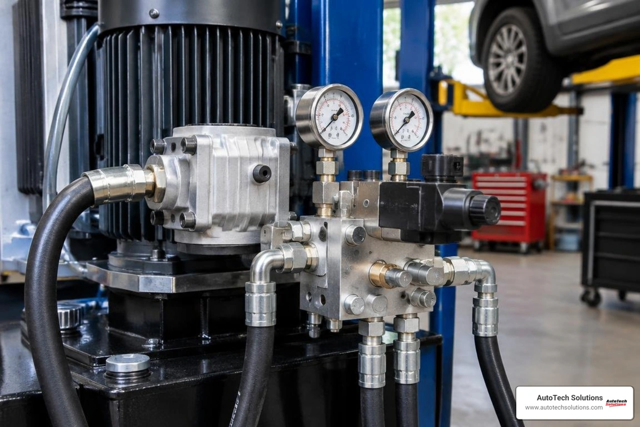
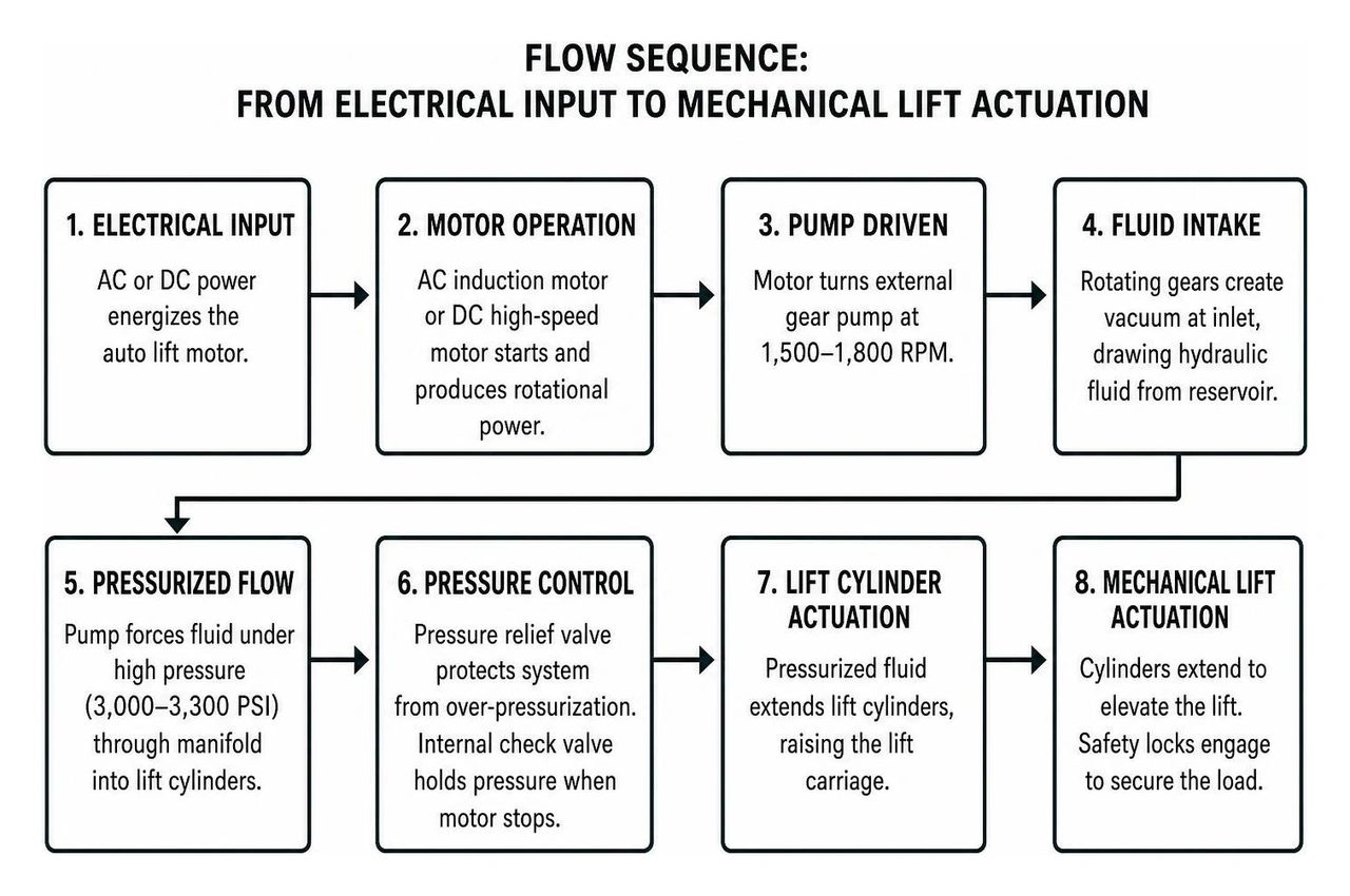
In standard fleet and dealership bays, AC induction motors operate on an intermittent duty cycle. Because a standard lift cycle lasts only 40 to 60 seconds, these motors are optimized for high starting torque rather than continuous runtime. When energized, the motor turns an external gear pump at speeds between 1,500 and 1,800 RPM. As the gears rotate, they mesh and create a partial vacuum at the pump inlet, drawing hydraulic fluid from the reservoir tank and forcing it under high pressure (typically 3,000 to 3,300 PSI) through the manifold block into the lift cylinders.
Advanced fast-rise configurations utilize DC battery-buffered systems. By pairing industrial high-output DC motors with onboard charging banks, these power units deliver upwards of 5 HP of lifting force on standard line power. This reduces full rise times from a traditional 65 seconds down to approximately 35 seconds, directly increasing throughput in rapid-lube and collision facilities.
Primary Components of the Hydraulic Power Unit Assembly
The power unit manifold integrates mechanical, electrical, and fluid circuits into a single modular block:
- External Gear Pump: Sized by displacement (commonly 4.3 cc/rev to 5.0 cc/rev), dictating the gallons-per-minute (GPM) delivery and overall carriage ascent speed.
- Fluid Reservoir: Heavy-duty polyethylene or steel tanks, sized between 3.0 and 4.0 gallons (10 to 15 liters), designed with internal baffled suction ports to prevent oil aerification.
- Lowering Valve: A manual pull-lever or electric 24V/120V solenoid valve that unseats an internal poppet, allowing fluid to return to the reservoir by gravity during descent.
- Internal Check Valve: Traps fluid pressure inside the hydraulic lines when the motor stops, holding the lift structure elevated until mechanical safety locks engage.
- Pressure Relief Valve: A calibrated, tamper-resistant internal spring-and-ball mechanism that opens if system pressure exceeds factory thresholds, preventing over-pressurization and avoiding premature hydraulic lift cylinder repair.
Single-Phase vs. Three-Phase Auto Lift Motor Configurations
Matching commercial shop power infrastructure to the power unit configuration is crucial for equipment longevity and motor thermal management:
| Specification | Single-Phase (1-Phase) Commercial Unit | Three-Phase (3-Phase) Heavy Duty Unit |
|---|---|---|
| Supply Voltage | 208–240V AC | 208–240V / 460–480V AC |
| Current Draw (Running) | 18 to 30 Amps | 6 to 12 Amps |
| Starting Mechanism | Start and/or Run Capacitors + Centrifugal Switch | Balanced 3-Phase Stator Windings (No Capacitors) |
| Starting Inrush Multiplier | 4x to 6x Full Load Amperage | 2x to 3x Full Load Amperage |
| Duty Cycle Resilience | Moderate (Thermal cooling required between cycles) | High (Continuous multi-bay cycle capability) |
| Ideal Bay Environment | Independent auto repair, fleet service bays | High-volume collision, municipal, heavy-truck bays |
Electrical Systems: Capacitors, Switches, and Wiring Specifications
The electrical system directing the hydraulic motor must withstand intense current spikes during initial motor startup. A single-phase electric motor utilizes specialized capacitor banks and contact switches to establish the rotational phase shift required to turn the rotor under full hydraulic load. Routine inspection of these control circuits is an essential element of ongoing car lift maintenance.
Start vs. Run Capacitors in Commercial Power Units
Single-phase power units rely on two distinct capacitor styles housed in moisture-resistant conduit enclosures along the motor shell:
- Motor Start Capacitors (300µF to 600µF, 250VAC to 330VAC): These components remain in the circuit for only a fraction of a second. They deliver a large microfarad surge to overcome the static friction and hydraulic head resistance of the gear pump. Once the motor hits 75% of operational RPM, an internal centrifugal switch or solid-state relay disconnects the start capacitor.
- Motor Run Capacitors (60µF to 80µF, 370VAC to 450VAC): These heavy-duty dielectric capacitors remain energized continuously while the lift button is pressed. They smooth the magnetic field across the stator windings, optimize motor running efficiency, and control heat buildup.

If a start capacitor suffers dielectric breakdown, the motor will emit a loud hum and draw locked-rotor amperage until the thermal overload trips, completely halting shop operation.
Sizing Standby Generators for Commercial Shop Lift Power
When running commercial shop lifts on standby generator backup, simple continuous power ratings are insufficient. A standard 2.2kW (3 HP) single-phase power unit draws roughly 2,200 watts while lifting at full capacity. However, starting that motor under load generates an inrush surge requiring 3 to 6 times the normal running current.
To prevent the voltage sag that causes magnetic contactors to chatter and motor windings to overheat, a commercial generator must deliver a minimum peak surge capacity of 3.5kW to 5.0kW dedicated per 3 HP lift motor. Facilities utilizing centralized backup systems must evaluate these peak inductive spikes across all bay equipment to prevent instantaneous generator breaker tripping.
Commercial Diagnostics: Sourcing and Replacing Failed Power Units
Diagnosing a non-functioning lift requires isolating electrical faults from hydraulic restrictions before initiating two post lift repair procedures.
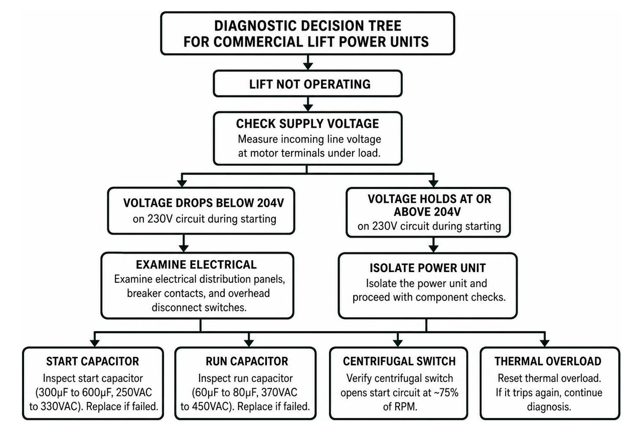
Diagnostic Steps for Auto Lift Motor and Power Unit Failure
When resolving power delivery issues, our technicians follow a standardized diagnostic routine consistent with our auto lift repair guide 2026:
- Supply Voltage & Drop Verification: Measure incoming line voltage at the motor terminals while under load. If line voltage drops below 204V on a 230V circuit during the starting sequence, examine electrical distribution panels, breaker contacts, and overhead disconnect switches.
- Capacitance Testing: Disconnect and safely discharge the capacitors. Using a digital multimeter set to capacitance mode, verify that the measured microfarads (µF) fall within ±10% of the rating stamped on the housing.
- Microswitch & Overhead Limit Continuity: Check continuity across the raise push-button microswitch and the overhead safety cutoff switch. Padded overhead shutoff bars incorporate a limit microswitch that interrupts control power if an elevated vehicle contacts the bar.
- Hydraulic Pressure Testing: Thread a 0–5,000 PSI pressure gauge into the manifold test port. Run the motor: if the motor operates at full speed but pressure fails to reach the manufacturer relief spec (typically 3,000 PSI), inspect the lowering valve for unseated debris, or evaluate the pump gears for internal bypass wear.
Universal vs. Manufacturer-Specific Power Unit Compatibility
Replacing an entire power unit requires evaluating more than physical dimensions. Key compatibility factors include:
- Mounting Flange Bolt Pattern: While many units share standard European or American bolt circles, column clearances vary significantly.
- Pump Displacement & Flow Rates: Replacing a 4.3 cc/rev pump with a larger displacement pump without verifying line diameters will increase fluid velocity, causing turbulence and overheating the hydraulic oil.
- Pressure Relief Rating: Installing a power unit calibrated to 3,500 PSI on a lift rated for 2,800 PSI risks structural overloading and cylinder seal blowouts.
Commercial Maintenance and Safety Protocols for Fleet Uptime
Maintaining hydraulic and electrical power unit systems protects technicians and maximizes commercial bay productivity. Shops should integrate power unit inspections into their overall preventative maintenance lift guide 2026 routines.
- Fluid Viscosity Inspections: Change hydraulic oil (typically ISO VG 32 or ISO VG 46) every 12 to 24 months. Degraded fluid forms sludge that clogs lowering valve orifices and accelerates gear pump wear.
- Terminal Torque Checks: Inductive vibration loosens terminal screws on push-button switches and capacitor posts over time, leading to high-resistance arcing.
- Mechanical Lock Calibration: Never allow hydraulic pressure alone to support an elevated vehicle. Always lower the carriage onto mechanical safety locks to relieve line pressure, which serves as a core strategy for downtime reduction lift repair.
Frequently Asked Questions About Commercial Lift Motors
What horsepower is required for commercial 2-post and 4-post lifts?
Most commercial 2-post and 4-post lifts with capacities between 8,000 lbs and 12,000 lbs require a 2.5 HP to 3.0 HP motor (2,200W rated power) operating at 208–240V single-phase or three-phase. Heavier 4-post commercial alignment lifts and industrial mobile column systems often utilize 4.0 HP to 5.0 HP power plants to sustain acceptable rise times under high tonnage.
Why is the hydraulic motor humming but failing to raise the carriage?
A loud motor hum without rotation is typically caused by a blown motor start capacitor, open centrifugal switch contacts, or severe supply voltage drop under load. If the electrical system checks out, mechanical failure—such as a seized gear pump or severe hydraulic lock caused by a jammed safety release—is the likely culprit.
Can hydraulic power unit components be interchanged across commercial brands?
Certain external accessories such as reservoir tanks, push buttons, and standard start capacitors can often be interchanged if voltage and microfarad ratings match. However, complete hydraulic manifold assemblies, lowering valve stems, and gear pumps must match the original manufacturer flow, displacement, and pressure specifications to maintain equipment safety certifications.
Conclusion
The motor and hydraulic power unit represent the active heart of your commercial shop lifts. Maintaining clean power delivery, testing capacitors regularly, and monitoring fluid pressure ensures reliable bay throughput day after day. When a power unit fails, identifying the correct motor specifications, displacement parameters, and electrical ratings prevents costly misdiagnoses.
AutoTech Solutions delivers comprehensive automotive equipment sales, service, and preventative maintenance across our branch network in Charlotte, NC, Raleigh, NC, Wade, NC, and Novi, MI. Our certified field specialists provide fast response times and rapid parts dispatch to keep your service bays operational. Contact our team to schedule an inspection or arrange professional commercial automotive lift installation for your facility.