When a Leaking Cylinder Stops Your Shop Cold
Hydraulic lift cylinder repair is the process of disassembling, resealing, and reassembling a lift's hydraulic cylinder to stop fluid leaks, restore lifting power, and eliminate dangerous cylinder drift.
Here's a quick overview of the repair process:
- Diagnose the failure — identify external leaks, internal bypass, or cylinder drift
- Gather tools — gland wrench, brass seal picks, torque wrench, seal kit matched to your lift model
- Depressurize and lock out — lower the lift, engage safety locks, follow lockout/tagout procedures
- Disassemble the cylinder — remove the head using the correct method for your cylinder type (wire ring or threaded head)
- Inspect components — check the barrel bore, piston rod, and chrome surface for scoring or damage
- Install new seals — replace all seals with a model-specific kit, lubricating with clean hydraulic oil
- Reassemble and torque — follow exact torque specifications for your locknut size
- Test under pressure — cycle the lift and verify there are no leaks before returning to service
Every minute a lift is down, your shop loses revenue and your technicians lose productive time. A leaking hydraulic cylinder is one of the most common culprits — and left unaddressed, what starts as a small fluid puddle under a two-post lift can escalate into a full cylinder failure or, worse, a safety incident.
The good news: most commercial lift cylinders can be rebuilt on-site with the right tools, the correct seal kit, and a clear understanding of your cylinder type. This guide walks through exactly how to do it — from diagnosing the failure to torquing the final locknut.
Learn more about Hydraulic lift cylinder repair:
Diagnosing the Need for Hydraulic Lift Cylinder Repair
Before we drag out the heavy toolboxes and start draining fluid, we need to know exactly what we are dealing with. In a commercial shop environment, hydraulic cylinder failures manifest in two distinct ways: external mess and internal failure. Identifying the exact nature of the failure helps us prepare the right parts and understand if the cylinder requires a straightforward repacking or a complete component overhaul.
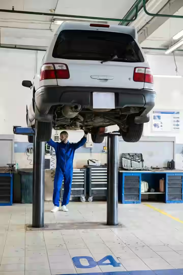
Understanding why these failures occur is the first step in robust Car Lift Maintenance. When we ignore minor symptoms, we invite catastrophic downtime. To keep your shop running smoothly, it helps to understand the Common Causes of Automotive Lift Downtime so you can catch issues before they halt your operations.
Identifying Cylinder Drift and Internal Bypass
When a commercial lift is raised to working height under load, locked on its controls, and slowly creeps downward over time, that is cylinder drift—a classic sign of internal bypass.
Internal bypass occurs when hydraulic fluid slips past the internal piston seals. In a perfect system, the piston seals form an airtight, high-pressure barrier that traps fluid on one side of the cylinder barrel to hold the load. When these seals wear out, harden, or get sliced by tiny pieces of debris, fluid slowly bypasses the piston and flows to the low-pressure side.
While the cylinder remains completely dry on the outside, the lift loses its ability to hold tonnage. It is worth noting that a drifting lift can also be caused by a failing load-holding valve or counterbalance valve. A great way to isolate the problem is to check if the drift occurs when the mechanical locks are disengaged and the system is held solely by hydraulic pressure. If the cylinder slowly sinks, those internal piston seals are almost certainly shot.
Recognizing External Fluid Leaks and Seal Wear
External fluid leaks are much easier to diagnose because they leave a physical footprint. If you spot a puddle of hydraulic fluid or Dexron III ATF accumulating around the base of your two-post lift columns, the rod seals and wiper seals have failed.
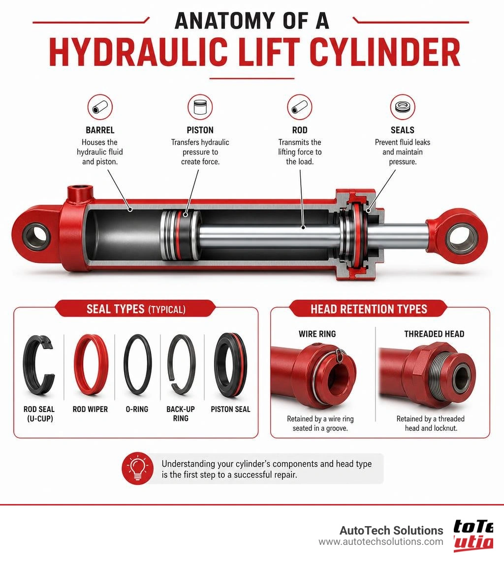
The rod seal is the primary high-pressure barrier located in the cylinder head (or gland) that prevents fluid from escaping as the polished chrome rod strokes in and out. The wiper seal, positioned just ahead of the rod seal, acts as a scraper to keep shop dust, metal shavings, and grime from entering the cylinder.
Once the wiper seal degrades, abrasive particles cling to the rod and slide right past, tearing the delicate polyurethane lips of the rod seal. This leads to immediate external leakage. If you notice a steady drip every time the lift is under pressure, it is time to schedule a rebuild before the fluid level drops low enough to cause jerky lift operation or pump cavitation.
Essential Tools and Preparation for Rebuilding Cylinders
Rebuilding a heavy-duty hydraulic cylinder in a commercial facility requires specialized equipment and precision. Using improper tools can ruin expensive shop components, scratch polished chrome surfaces, and guarantee that new seals will fail prematurely under commercial operating pressures.
For a deeper dive into industrial-grade methodologies, you can read more about How to Rebuild Hydraulic Cylinders to see how precision engineering plays a role in fluid power restoration.
Required Commercial Shop Tooling
To execute a professional-grade rebuild, make sure your shop’s tool crib is stocked with the following specialized equipment:
- Adjustable Gland Nut Wrench (Spanner Wrench): Standard models like the 1266 or 7463 are designed to fit the pinholes on cylinder glands without slipping and stripping the metal.
- Brass or Plastic Seal Picks: Never use steel screwdriver tips or steel picks to remove old seals. A single microscopic scratch in a seal groove creates a permanent leak path that no new seal can plug.
- Torque Wrench and Torque Multiplier: Piston locknuts require immense torque to prevent them from backing off under high operating pressures.
- Soft-Faced Mallet and Brass Punch: Essential for tapping components loose without causing burrs or deformation.
- Emery Cloth (400 to 600 grit): For polishing out minor surface burrs on metal parts.
- Clean Solvent and Lint-Free Rags: Cleanliness is paramount. Roughly 80% of all hydraulic system failures are directly caused by fluid contamination.
If you find that your cylinder rods or internal hardware are too badly damaged to salvage, you can source high-quality replacement components by browsing Car Lift Parts For Sale.
Safety Protocols and Depressurization
Working around high-pressure hydraulics demands strict adherence to safety protocols. Before you loosen a single bolt or hose connection, you must enforce the Zero Energy Rule:
- Lower the Lift Completely: Never work on a cylinder while a lift carriage is raised unless the carriages are securely resting on their mechanical safety locks.
- Lockout/Tagout (LOTO): Disconnect the main power supply to the hydraulic power unit and tag the switch to prevent anyone from accidentally activating the pump.
- Relieve Residual Pressure: Cycle the manual lowering valve several times to bleed off any pressure trapped in the hydraulic lines.
- Guard Against Fluid Injection: High-pressure hydraulic fluid can easily penetrate human skin, causing severe, limb-threatening tissue damage. Never use your bare hands to feel for leaks or check ports.
Step-by-Step Guide to Wire Ring Cylinder Repair
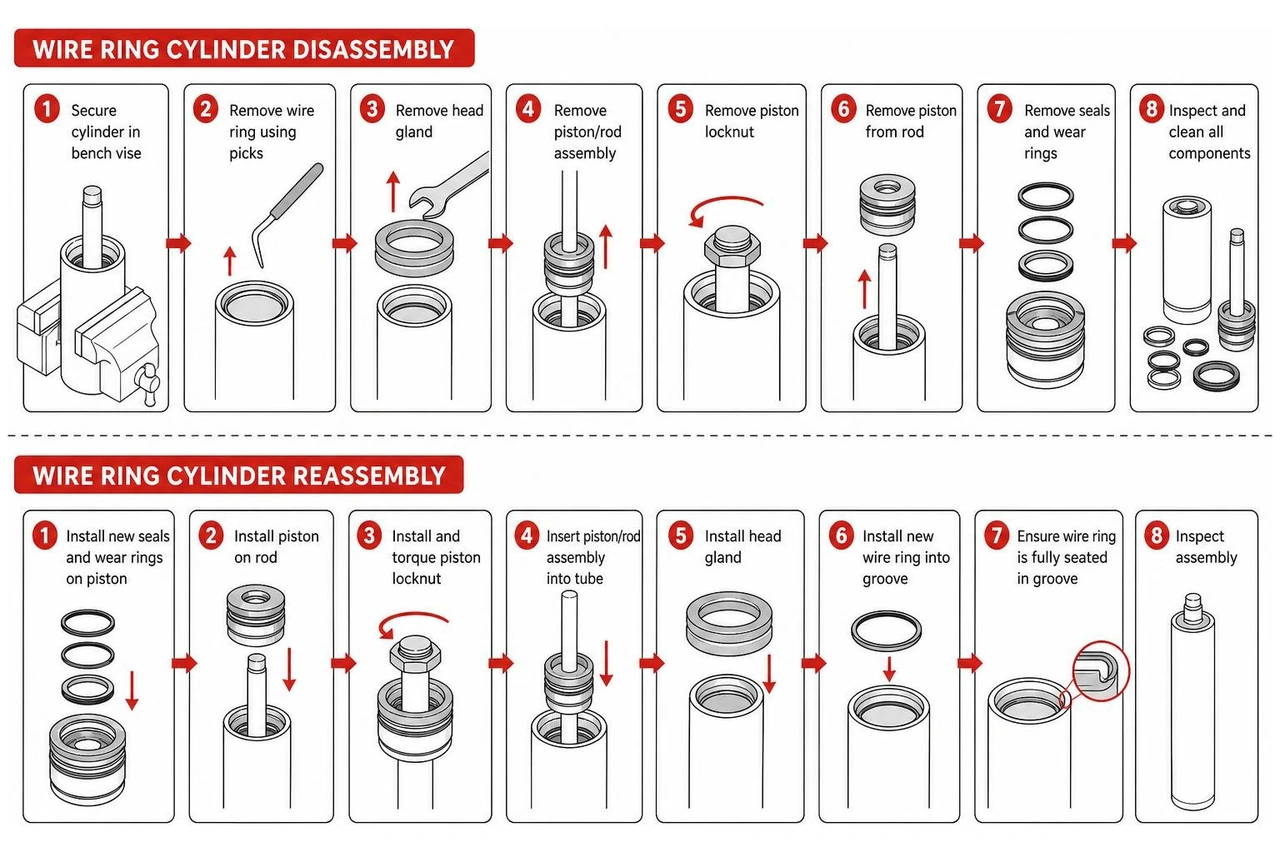
Hydraulic lift cylinders generally fall into two categories based on how their heads are retained: wire ring style and threaded head style. Wire ring cylinders are highly common in commercial automotive lifts. They use an internal wire ring nested inside a machined groove within the cylinder tube to lock the head in place.
Disassembly of Wire Ring Cylinders
Disassembling a wire ring cylinder requires patience and a specific sequence to avoid damaging the internal retention groove:
- Secure the Cylinder: Clamp the cylinder in a heavy-duty bench vise. Always clamp onto the mounting clevis or the heavy end cap — never clamp the middle of the cylinder tube, as you can easily oval or distort the barrel.
- Expose the Groove: Use a soft-faced mallet and a brass punch to gently tap the cylinder head (gland) inward, pushing it about 1/2 inch into the cylinder tube. This movement exposes the internal wire ring nested in the tube’s inner groove.
- Insert the Plastic Removal Ring: Your model-specific seal kit will include a thin, flat plastic removal ring. Straighten the plastic ring to remove any kinks, then insert it directly into the internal groove where the wire ring sits.
- Extract the Wire Ring: Pull the cylinder rod outward. As the head slides back toward the opening, it will ride up onto the plastic removal ring, forcing the internal wire ring out of its groove and allowing you to slide the entire rod, piston, and head assembly completely out of the tube.
Reassembly and Seating the Wire Rings
Putting a wire ring cylinder back together requires precision to ensure the retention mechanism locks perfectly:
- Lubricate and Slide: Coat the newly sealed piston and head assembly with clean hydraulic oil. Carefully slide the piston into the barrel, followed by the head.
- Compress the Inner Wire Ring: Position the internal wire ring over the head. You will need to use a standard band clamp to compress the wire ring tightly against the head.
- Slide and Seat: Push the head assembly into the cylinder tube. As the head enters the tube, loosen the band clamp slightly so it can slide off as the compressed wire ring enters the barrel.
- Achieve Flush Seating: Push the head in until the wire ring snaps firmly into the internal tube groove. Critical Warning: You must ensure the cylinder head is completely flush and that the wire ring is fully expanded into its seat. If the head is not flush, the ring will not lock, and the entire rod assembly will blow out catastrophically when hydraulic pressure is applied.
Step-by-Step Guide to Threaded Head Cylinder Repair
Threaded head cylinders utilize an end cap or gland that threads directly into or onto the cylinder barrel. These are highly robust and are frequently found on heavy-duty collision repair equipment and larger capacity vehicle lifts.

To understand the engineering behind these heavy-duty assemblies, check out How to Repair Hydraulic Cylinder for professional insights on restoring threaded components.
Disassembling Set Screw and Locking Ring Styles
Many threaded cylinder heads feature an auxiliary locking mechanism, such as a small set screw or an external locking ring, to prevent the head from backing out during high-vibration operations.
- Remove the Set Screw: Locate and remove the set screw on the side of the cylinder tube using an Allen wrench. Failing to do this before spinning the head will ruin the threads on both the head and the barrel.
- Unscrew the Gland: Fit your adjustable spanner wrench into the pinholes of the head. Apply steady, counterclockwise pressure to unscrew the gland. If the head is stubborn, apply gentle heat (around 300°F) to break down any factory threadlocker, but be careful not to overheat and melt the internal seals if you plan to inspect them first.
- Extract the Rod Assembly: Once the threads are fully disengaged, pull the rod straight out of the barrel. Be careful to support the weight of the rod so it doesn't drag across the threads of the barrel, which can nick the polished chrome.
Reassembling and Torquing the Threaded Head
Reassembly is the reverse of disassembly, but with a strict focus on torque specifications:
- Apply Anti-Seize: Clean the threads thoroughly and apply a light coat of anti-seize or a medium-strength threadlocker, depending on the manufacturer's guidelines.
- Torque the Gland Cap: Thread the head back into the barrel by hand to avoid cross-threading. Use your spanner wrench and a torque wrench to tighten the threaded head end cap to the standard specification (typically 440 lb.ft / 600 N.m for standard commercial lifts).
- Secure the Set Screw: Reinstall the set screw and torque it to 6 lb.ft / 8 N.m to lock the gland in place.
- Torque the Piston Locknut: When reinstalling the piston onto the rod, you must use a new prevailing torque locknut (or clean and apply red Loctite to a standard high-grade nut) and torque it according to its size. Refer to the table below for precise torque values:
| Locknut Thread Size | Torque Value (lb.ft) | Torque Value (N.m) |
|---|---|---|
| 3/8" - 24 UNF | 25 - 30 | 35 - 42 |
| 1/2" - 20 UNF | 40 - 60 | 55 - 80 |
| 5/8" - 18 UNF | 95 - 105 | 130 - 140 |
| 3/4" - 16 UNF | 175 - 225 | 240 - 305 |
| 1" - 14 UNF | 300 - 380 | 405 - 515 |
| 1 1/2" - 12 UNF | 700 - 800 | 950 - 1085 |
| 1 3/4" - 12 UNF | 800 - 900 | 1085 - 1220 |
Component Inspection, Honing, and Seal Installation
Once the cylinder is fully disassembled, you must thoroughly inspect every single hard component. Simply putting new seals into a damaged cylinder barrel is a waste of time and money — the physical defects will shred the new seals on the very first stroke.
For complex repairs where the barrel or rod is severely damaged, relying on a professional Two Post Lift Repair service ensures your equipment is restored to OEM safety standards.
Inspecting the Barrel, Piston, and Rod
Lay all components out on a clean, lint-free workbench and perform these critical quality checks:
- Visual and Tactile Inspection: Inspect the polished chrome surface of the piston rod. Any scratch, pit, or nick deep enough to catch a fingernail or tool edge will slice through your new rod seal. Minor burrs can be polished out with a very fine (600-grit) emery cloth, but deeply gouged or bent rods must be replaced.
- Protect the Chrome: When clamping the rod in a vise to remove the piston nut, never clamp directly onto the polished chrome surface. Always use soft copper, brass, or aluminum jaw protectors, or clamp onto the mounting clevis end.
- Inspect the Cylinder Bore: Peer inside the cylinder barrel with a flashlight. Look for scoring, rust, or a glazed, ultra-smooth surface.
- Hone the Barrel: Over time, the inside of the barrel becomes glazed, which prevents hydraulic oil from clinging to the walls to lubricate the seals. Use a professional cylinder hone with plenty of honing oil to lightly deglaze the bore. Your goal is to create a 45-degree cross-hatch pattern with a surface roughness of 16 to 32 micro-inches (Ra). This microscopic texture holds a thin film of oil that keeps the seals lubricated and extends their lifespan. Wash the barrel with hot, soapy water afterward until a clean white rag comes out spotless.
Precision Seal Orientation and Installation
When installing your new seal kit, follow these best practices for a leak-free assembly:
- Understand Seal Direction (The Lip Rule): Hydraulic U-cup seals are highly directional. The open side of the "U" (the side with the lips) must always face the source of the hydraulic pressure. When pressure hits the open side, it forces the lips outward against the sealing surfaces, creating a tighter seal. Installing a U-cup backward will cause immediate, massive leakage.
- Soften and Seat PTFE Seals: Teflon (PTFE) piston seals can be stiff and difficult to stretch over the piston. Warm them up in clean, warm hydraulic oil to make them pliable (never use boiling water, as moisture degrades certain urethanes). Once stretched and installed into the piston groove, use a piston ring compressor or a specialized calibration sleeve to resize the seal back to its original outer diameter.
- Protect Seals During Installation: Before sliding the gland or piston over the threaded ends of the rod, wrap the threads with electrical tape or masking tape. This prevents the sharp metal threads from slicing the delicate lips of your new seals. Lubricate all seals and the inside of the barrel liberally with clean hydraulic oil or Dexron III ATF before final insertion.
Frequently Asked Questions about Hydraulic Lift Cylinder Repair
What tools are required for hydraulic lift cylinder repair?
To perform a professional-grade rebuild, you will need an adjustable spanner wrench (gland nut wrench), brass or plastic seal picks, a torque wrench, a soft-faced mallet, a brass punch, fine emery cloth, and clean hydraulic oil for lubrication. Never use steel screwdrivers or pipe wrenches, as they will damage polished surfaces and ruin seal grooves.
How do you identify a wire ring vs. threaded head hydraulic lift cylinder repair?
Look closely at the cylinder head where the rod exits the barrel. A wire ring cylinder will have a smooth head that sits slightly inside the tube, with no visible threads, and is held in place by an internal wire ring. A threaded head cylinder will feature a gland cap with pinholes or flat notches designed for a spanner wrench, and it may also have a small locking set screw on the side of the barrel.
Why is it critical to insert the cylinder head flush with the tube?
On wire ring cylinders, the head must be pushed in completely flush with the tube opening to allow the internal wire ring to fully expand and seat into its machined groove. If the head is not flush, the ring will only partially engage, causing the entire head and rod assembly to blow out under high pressure, resulting in a catastrophic lift failure and severe safety hazards.
Conclusion
Taking a proactive approach to Hydraulic lift cylinder repair is one of the smartest ways to keep your commercial shop safe, efficient, and profitable. By catching minor weeping seals early and executing a precise rebuild, you avoid the extreme costs of unexpected equipment downtime and ensure your technicians are working under safe, reliable machinery.
However, we know that running a busy commercial automotive shop means your time is highly valuable. If you prefer to leave the heavy lifting, precision honing, and safety compliance to the experts, AutoTech Solutions is here to help.
As a premier one-stop-shop for commercial automotive equipment sales, installation, and service, we specialize in minimizing shop downtime. Our expert service crews provide rapid repair response and comprehensive preventative maintenance across Michigan and the Carolinas, with physical locations ready to serve you in:
- Novi, MI
- Charlotte, NC
- Raleigh, NC
- Wade, NC
Whether you need a rapid emergency repair, a certified lift safety inspection, or professional equipment support, we’ve got your shop covered.
For more professional tips on maintaining your shop infrastructure, check out our Auto Lift Repair Guide 2026. Ready to schedule professional service? Contact us today through our Professional Equipment Support Services page and let us keep your business moving forward.