

Evaluating the Blue Point Alignment Machine: Core Technology and Engineering
Modern commercial automotive facilities require diagnostic precision that traditional mechanical arms and pendulum gauges simply cannot deliver. The engineering behind the Blue-Point line centers on digital optical tracking. Using high-resolution, ultra-high-definition (UHD) cameras—up to 5 megapixels on advanced configurations—the system continuously tracks optical reflections from target plates mounted to each wheel assembly.
This approach relies heavily on modern camera wheel alignment principles, where image processing algorithms generate real-time 3D spindle modeling. Instead of calculating angles through analog levels, the software monitors spatial orientation down to fractions of a millimeter. Technicians receive immediate visual feedback via the Vehicle Orientation Directional Indicator (V.O.D.I) system, which uses graphic prompts on the primary display to guide target placement, rolling compensation, and mechanical adjustments without forcing the operator to walk back and forth to the console.

At the software layer, Blue-Point systems integrate dedicated diagnostic platforms like Pro42. This software references extensive vehicle specification databases to calculate total toe, individual toe, setback, steering axis inclination (SAI), included angle, and thrust angle metrics. It offers an extensive camber adjustment range of ±10 degrees, accommodating standard passenger alignments, modified commercial fleet vehicles, and frame-straightened collision repairs. Powered by a standard 100–240V single-phase electrical supply, these machines integrate cleanly into existing shop electrical infrastructure without requiring dedicated high-voltage drops.
Blue Point Alignment Machine Models: Pyramid vs BWA 200 Series
When outfitting a commercial facility, choosing between alignment configurations depends on bay architecture, lift setup, and production volume. The primary commercial offerings within the Blue-Point lineup include the Pyramid series and the BWA 200 imaging system.
The Blue-Point Pyramid Wheel Aligner is engineered for heavy-duty production bays requiring broad vehicle compatibility. It utilizes a durable tower design, robust passive XD targets, and specialized software routines like EZ-TOE for turning wheels during adjustment while maintaining live tracking.
In comparison, the Blue-Point BWA 200 Imaging Wheel Alignment platform focuses on compact floor optimization. It features a slim-post structural mount with adjustable camera height settings, an embedded solid-state Windows 10 industrial PC, and AC100 GEN II universal wheel clamps designed to grip tires securely without marring expensive alloy rims.
| Feature / Specification | Blue-Point Pyramid Series | Blue-Point BWA 200 Series |
|---|---|---|
| Camera Configuration | Multi-camera UHD array / 5 MP | High-resolution XD camera beam |
| Target Technology | Passive XD optical targets (no electronics) | Lightweight diamond-cover XD targets |
| Wheel Size Compatibility | 11" – 22" (expandable to 26") | 12" – 22" (expandable with extensions) |
| Track Width Range | 48" – 96" (122 – 244 cm) | 48" – 96" (122 – 244 cm) |
| Wheelbase Range | 79" – 180" (201 – 457 cm) | 79" – 180" (201 – 457 cm) |
| Operating System | Industrial Windows-based platform | Embedded Windows 10 OS on SSD |
| Adjustment Features | EZ-TOE, live caster sweep, ride height | Pro42 diagnostic flow, live graphic guide |
| Power Requirements | 120/230V, 1 Ph, 50/60 Hz | 100–240V, 1 Ph, 50/60 Hz |
| Bay Footprint Needs | Full-size dedicated alignment lane | Compact slim-post, flexible bay layout |
Sensor Accuracy, Target Durability, and Calibration Requirements
In a busy automotive shop, tools get bumped, dropped, and exposed to oil mist. Traditional corded electronic sensor heads contain fragile circuitry, internal inclinometers, and batteries that fail when subjected to rough handling. Blue-Point addresses this vulnerability by using non-electronic XD target plates.
These passive targets are constructed from high-impact composite materials with protective outer housings. Because there are no wires, internal circuit boards, or glass lenses inside the wheel targets, dropping a plate onto concrete does not shatter electronic sensors or disrupt calibration. Routine operational longevity requires simple target hygiene—wiping dust and grease from the optical faces using a soft, non-abrasive cloth.
Maintaining baseline accuracy also involves inspecting structural wheel alignment machine parts, such as clamp pins, turntable slip plates, and camera mounting hardware. Modern 3D imaging systems maintain factory calibration far longer than older mechanical systems because the optical cameras remain stationary on a rigid crossbeam or post. Provided the camera structure is isolated from severe mechanical impacts and room-temperature shifts are managed, annual precision checks and standard runout compensation protocols are sufficient to keep readings certified to OEM tolerances.
Step-by-Step Commercial Bay Workflow and Setup Procedures
Efficiency in the service lane relies on standardized procedures. A properly trained technician using a Blue-Point 3D system can move from initial positioning to live measurement readings in under two minutes:
- Staging and Bay Entry: Center the vehicle onto the alignment rack or lift. Ensure tires are inflated to door-placard specifications, disengage turnplate lock pins, and install rear slip-plate pins for drive-on stability.
Mounting Wheel Clamps: Attach the four AC100 clamps with their respective XD target plates securely to the outer rim lips. Ensure the clamps seat evenly to eliminate mechanical runout errors.
Vehicle Positioning and Rolling Compensation: Push the vehicle backward and forward smoothly across the turntables as prompted by the V.O.D.I software interface. This short rolling motion calculates true rotational axes and compensates for any rim irregularities or clamp offsets without requiring bay jacks.
- Tool and Accessory Placement: Install the brake pedal depressor to lock hydraulic pressure and prevent rotation during steering sweeps. Fit the steering wheel holder to maintain true center.
- Specification Selection and Sweep: Select the exact year, make, model, and trim sub-package from the Pro42 database. Perform a 20-degree steering sweep to measure live caster, SAI, and turning radius angles.
- Live Adjustment and Quality Verification: Review out-of-spec parameters highlighted in red on the monitor. Make mechanical tie-rod, eccentric bolt, or control arm shim adjustments using real-time screen prompts. When all angles show green within manufacturer tolerances, print the final customer report and clear the lane for the next vehicle.
Handling Non-Standard Wheelbases, Classic Frames, and Collision Rebuilds
Commercial bays encounter a diverse range of chassis designs, from lowered sports sedans and long-wheelbase cargo vans to vintage chassis and collision repair rebuilds. Blue-Point systems accommodate this variety through expansive hardware parameters. Standard wheel clamps handle 11- to 22-inch rims, with optional clamp extensions expanding coverage up to 26 inches for custom fleet wheels. Track width support spanning 48 to 96 inches and wheelbase ranges from 79 to 180 inches ensure light commercial vans and utility trucks fit comfortably on the rack.
When measuring vintage chassis or structural repairs, technicians frequently encounter non-standard wheel openings, aftermarket control arms, or severe setback where the front axle is pushed out of square. By combining live 3D calculations with manual ride-height entry modules, the software isolates frame distortion from suspension misalignment. This structural diagnostics capability makes the platform valuable during collision repair alignment system routines, allowing technicians to verify axle offset and frame centering before completing final mechanical adjustments.
Commercial Advantages, Limitations, and Bay Troubleshooting
While 3D camera systems provide distinct throughput benefits, commercial facilities must manage specific environmental and operational variables to avoid bay bottlenecks:
- Optical Line-of-Sight Interruptions: Because the system relies on line-of-sight tracking between the high-definition cameras and the target plates, raised lift arms, open vehicle doors, or unorganized tools hanging off the rack can obstruct the view. Technicians must maintain a clear optical pathway between the overhead beam and the wheels.
- Ambient Lighting and Glare Control: Strong, unshielded halogen bay lamps or direct sunlight reflecting off glossy floor finishes can flood optical camera sensors. Positioning alignment racks away from open east- or west-facing bay doors or adjusting fixture diffusion prevents optical tracking dropouts.
- Software and System File Integrity: Blue-Point systems running embedded Windows platforms benefit from fast boot times on internal solid-state drives. Shops should maintain regular database backups and avoid unapproved third-party software installations that could corrupt diagnostic driver communication.
- Hardware Wear on Mechanical Accessories: Slip plates and mechanical turntables accumulate road grime, tire grit, and salt over time. Failing to clean and lubricate internal ball bearings causes rotational drag, leading to false caster readings during steering sweeps.
When complex hardware faults or optical communication errors occur, relying on established automotive equipment repair specialists ensures factory camera alignment is restored without extensive lane downtime.
Financial Analysis and Commercial Bay Investment Strategy
Investing in high-end alignment infrastructure requires evaluating ticket volume, bay turnaround times, and complementary equipment pairings. Alignment services represent one of the highest margin operations in commercial automotive repair, boasting minimal consumable costs compared to oil changes or brake pad replacements.
A productive shop can pair an alignment machine alongside high-volume wheel balancer equipment to create a dedicated tire service center. Using strategic frameworks found in our automotive equipment solutions guide 2026, shop owners can structure service bays to capture tire sales, seasonal changes, suspension rebuilds, and preventive alignments within a streamlined production loop.
Calculating ROI for a Blue Point Alignment Machine in High-Volume Bays
The primary driver of return on investment (ROI) with 3D optical technology is cycle time reduction. By cutting alignment setup from 10–15 minutes down to 2–3 minutes, a shop performing five alignments daily saves approximately an hour of technician labor every day while increasing lane capacity.
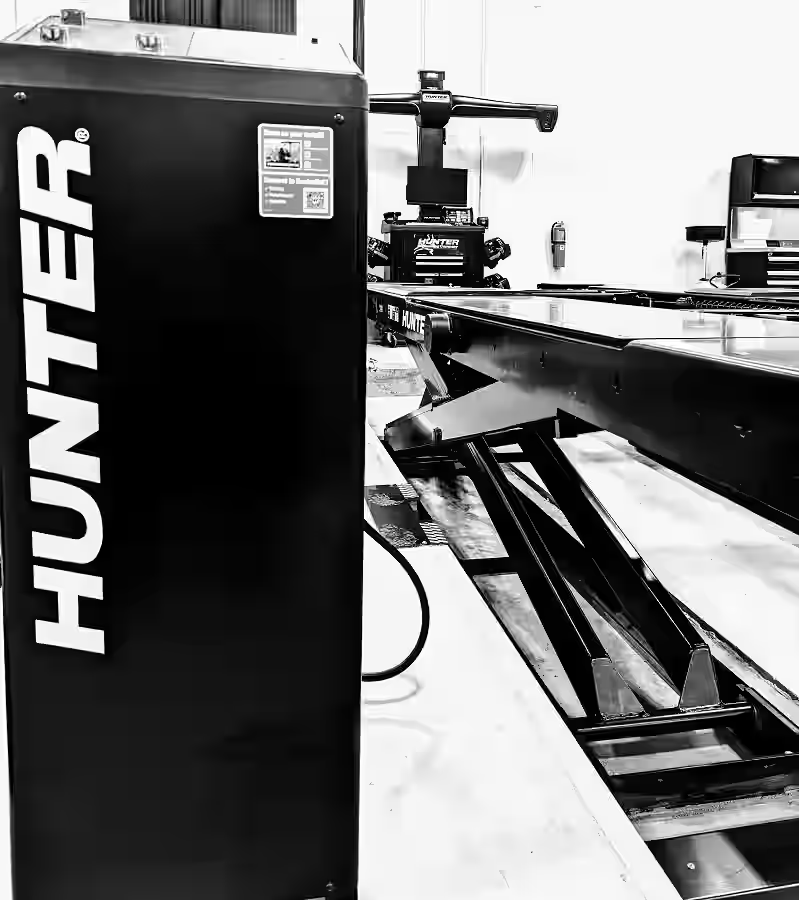
Beyond direct alignment revenue, providing customers with graphic before-and-after specification reports increases conversion rates on profitable mechanical repairs. Highlighting red out-of-spec angles identifies worn ball joints, bent tie rods, and blown struts that would otherwise leave the shop undetected.
Frequently Asked Questions About Blue Point Alignment Systems
What rim sizes and vehicle wheelbases can Blue Point alignment systems accommodate?
Standard configurations support rim diameters from 11 to 22 inches, with adapter kits expanding capacity up to 26 inches. Track widths from 48 to 96 inches and wheelbases from 79 to 180 inches allow commercial shops to service compact passenger cars, commercial utility vans, and light-duty fleet trucks on the same rack.
Does a 3D imaging alignment system require frequent field recalibration?
Because passive XD targets contain no internal electronic sensors, normal shop handling will not disrupt their accuracy. The stationary optical cameras feature fixed solid-state arrays that maintain calibration over extended periods. Periodic annual calibration verifications are standard practice to confirm camera-to-rack spatial geometry.
What electrical and bay footprint specifications are required for installation?
Most systems operate on a standard single-phase 100–240V AC power connection (50/60 Hz). Bay requirements depend on lift layout, but typically require a clear working lane length of 16 to 20 feet and a camera-to-turnplate focal distance of at least 68.5 inches (1.73 meters) for optimal optical tracking.
Conclusion
Upgrading your commercial facility with modern 3D optical diagnostic systems is a proven way to eliminate bay bottlenecks, improve mechanical repair sales, and increase customer satisfaction. At AutoTech Solutions, we specialize in end-to-end commercial bay modernization, from site assessment and equipment sales to certified commercial installation and preventative maintenance.
We understand that an idle bay costs your business money, which is why our certified technicians provide fast repair support and ongoing service across our facilities in Novi, MI, as well as Charlotte, Raleigh, and Wade, NC. To learn more about modernizing your tire and mechanical service bays, explore our wheel service equipment guide 2026 or contact our technical team to schedule an on-site equipment consultation.