
Choose a Camera Wheel Alignment System Built for Shop Throughput
Camera wheel alignment systems use 3D machine vision to track optical targets at the service position, helping professional automotive shops measure alignment angles quickly and consistently.
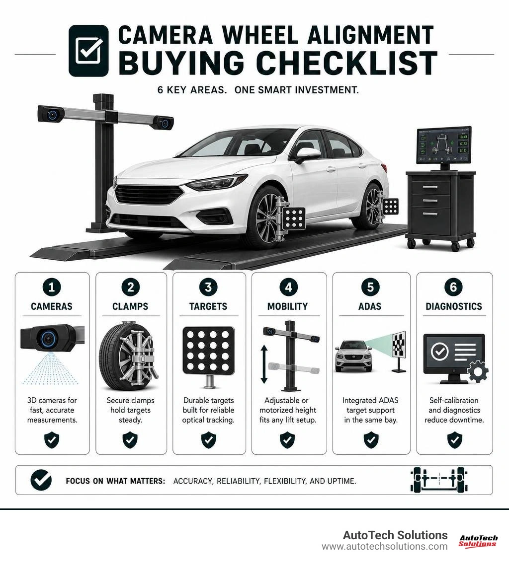
For a fast buying decision, look for a system with:
- 3D cameras and durable targets for reliable optical tracking
- Secure clamping assemblies that hold targets steady during measurement
- Motorized or adjustable camera height to work with different lift positions
- Continuous runout compensation to reduce stops in the measurement process
- Self-calibration and diagnostics to protect accuracy and limit downtime
- ADAS target integration if your facility performs sensor calibration in the same bay
- Portable or folding camera arms when equipment must move between bays
The right setup is not simply the one with the most features. It is the one that fits your bay layout, lift configuration, service volume, and maintenance capacity. Modern systems can collect repeated target-position data at more than 20 poses per second, while advanced designs can combine alignment measurement and ADAS target positioning on one shared support structure.
This roundup compares the camera wheel alignment features that matter most for productive, accurate commercial service operations. AutoTech Solutions Staff brings practical shop-equipment experience to help facilities select, install, and support the right system.
Core Mechanics of Camera Wheel Alignment Systems
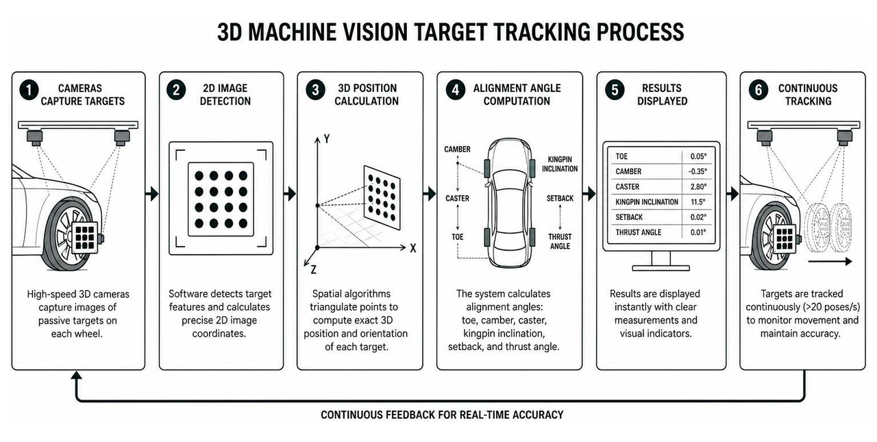
Understanding how camera wheel alignment systems work begins with machine vision technology. Rather than using structured light projections or lasers that require strict physical alignment and present optical safety risks, modern 3D aligners utilize high-speed optical camera arrays. These cameras record digital images of passive geometric targets mounted directly to the vehicle's wheels.
The core processing software relies on complex spatial algorithms to translate 2D image coordinates into precise 3D spatial representations. Modern systems can determine toe, camber, caster, kingpin inclination, setback, and thrust angle in seconds. As highlighted in innovations like Wheel toe and camber measurement system (US Patent 9702694), vision processing can detect grayscale contrast variations—such as the distinct boundary between a dark rubber tire and a metallic rim—or calculate the elliptical deformation of a circular wheel surface as it turns away from the camera plane. When a circular rim rotates out of a perpendicular orientation relative to the optical lens, its circular profile projects into an ellipse within the captured image. The central processing unit computes the orientation of that ellipse relative to the wheel’s rotational z-axis, isolating toe and camber offsets down to fractions of a degree.
For a complete breakdown of internal components and replacement hardware, consult our detailed breakdown of Wheel Alignment Machine Parts.
Core Components: Cameras, Targets, and Clamping Assemblies
A high-performance machine vision alignment rig depends on three synchronized physical components working together seamlessly:
- High-Resolution Optical Cameras: Fixed or motorized crossbeam enclosures house digital cameras equipped with high-performance CMOS or Scientific Image (SI) sensors. In standard fixed configurations, alignment cameras are mounted approximately 100 inches apart on a crossbeam and positioned roughly 100 inches in front of the vehicle lift.
- Passive Reflective Target Plates: Passive targets feature specialized high-contrast geometric pattern plates (often checkerboard designs). Common dimensions include 14x14 cm targets for front wheels and 27x27 cm targets for rear wheels, built at approximately 16 mm thickness to remain rigid without adding unneeded weight to the wheel assembly.
- Precision Clamping Assemblies: Wheel clamps attach directly to the vehicle's tire or wheel rim, establishing an unyielding baseline relative to the hub center.
If a clamp suffers from mechanical wear or sits improperly off-center, target movement will corrupt spatial calculations. Technicians must inspect clamping pins and utilize built-in spirit level indicators to ensure perpendicular mounting against the wheel face prior to recording baseline geometry.
High-Speed Data Collection and Non-Stop Positioning
Legacy alignment equipment required time-consuming manual steps where technicians had to stop the vehicle precisely at preset angular intervals (such as stopping at zero, 90, 180, and 270 degrees) to complete runout compensation. Modern 3D camera aligners utilize continuous optical sampling that completely eliminates these stopping steps.
Modern machine vision camera suites execute continuous image processing at rates exceeding 20 poses per second. During continuous rolling runout procedures, the system captures dynamic target images continuously as the vehicle rolls across the rack surface.
Key operational benchmarks during continuous rolling runout include:
- The system calculates at least one discrete target pose for every 5 degrees of wheel and target rotation without forcing a pause.
- When rolling the vehicle swiftly along the rack, the optical processors capture approximately 20 distinct target poses.
- Data acquisition accumulates continuously until each wheel traverses an elapsed angle of rotation of at least 35 degrees.
This continuous capture stream allows technicians to roll the vehicle smoothly, perform a continuous caster swing, and view immediate alignment measurements on the console screen without stopping mid-procedure.
Key Features of Modern Camera Wheel Alignment Equipment
Modern alignment bay equipment is designed to streamline workflow and enhance technician comfort. Variable-height motorized camera beams are among the most significant operational upgrades in modern service centers. In conventional aligners, fixed camera beams mounted high above the shop floor (often rising over 100 inches when servicing raised vehicles) require rigid mounting posts and limit sightlines when the lift is lowered to comfortable working heights. Motorized tracking beams adjust automatically or respond to single-keystroke commands from the main console PC keyboard. This allows shops to take roll-on measurements at floor level and raise the vehicle lift to an comfortable ergonomic working height while the camera beam automatically moves in sync to maintain line-of-sight visual connection with the targets.
Furthermore, dynamic diagnostic algorithms—such as those covered in Wheel aligner with advanced diagnostics and no-stop positioning (US Patent 11933606)—continually check for underlying structural variables like alignment rack twist or floor unlevelness before alignment values are logged.
Integrated ADAS Target Systems and Camera Wheel Alignment Stands
As Advanced Driver Assistance Systems (ADAS) become standard across modern vehicle fleets, shops face significant space challenges when organizing separate alignment bays and ADAS calibration areas. Forward-facing camera, radar, and LiDAR sensors require physical target frames positioned precisely relative to the vehicle’s thrust line and geometric centerline.
Innovative configurations, like the framework detailed in Vehicle wheel alignment measurement system camera and ADAS calibration support structure (US Patent 11692818), directly address this shop bottleneck by integrating both functions into a single structure:
- Unified Floor Footprint: Mounting the camera crossbeam and ADAS calibration target fixtures onto a shared vertical support structure eliminates equipment conflicts in tight service bays.
- Automated Target Positioning: The primary alignment cameras capture the exact spatial pose of the vehicle relative to the frame stand. The system's processing unit computes required target placement offsets and can guide or actuate multi-axis adjustment mechanisms across elevation, pitch, yaw, and roll.
- Floor Indicia Projection: Modern support frames can project visual indicators directly onto the floor surface, providing guided positioning for technicians moving calibration hardware into place.
This integration allows a commercial shop to perform complete 4-wheel camera alignment procedures and calibrate forward-facing ADAS equipment in a single, efficient workflow within the same service bay.
Portable Camera Wheel Alignment Configurations and Self-Calibration
Fixed camera towers bolted to concrete shop floors offer solid stability, but they tie up high-revenue service bays when vehicles wait for backordered suspension parts. Portable, mobile camera alignment units solve this bottleneck by bringing 3D vision technology to any available lift or flat service area.

Mobile alignment systems utilize unique engineering designs to achieve bay-to-bay flexibility:
- Collapsible Camera Arms: Standard rigid camera crossbeams exceed 100 inches in width and 80 inches in height, making them too bulky to navigate through shop doorways or crowded aisles. Portable alignment systems feature folding or retractable camera arms that narrow the overall machine footprint, allowing easy transport between service bays.
- Independent Self-Calibrating Camera Pods: Rather than relying on a heavy, fixed horizontal beam to lock camera geometries in place, mobile systems utilize independent camera pods. Each pod incorporates cross-facing calibration cameras and target arrays that continually track the spatial relationship between independent units. The machine performs ongoing self-calibration while in use, compensating for surface vibrations or slight repositioning without requiring manual calibration.
When workflow demands shift, a mobile system can be moved across the shop floor in minutes, keeping work flowing through every bay.
Advanced Diagnostics and Troubleshooting Camera Accessories
Even high-end 3D machine vision alignment equipment relies on clean optical paths and tight mechanical connections to maintain accuracy. When sensor signals fail or measurement errors occur, systematic troubleshooting keeps bay downtime to a minimum.
When complex hardware issues occur, our technicians deliver rapid hands-on support through our dedicated Service Repair and Equipment Support teams, serving commercial facilities across Michigan and the Carolinas.
Resolving Wheel Wobble, Rack Twist, and Runout Diagnostic Errors
Inconsistent measurement readings are frequently caused by mechanical factors around the alignment lift rack rather than internal optical sensor defects. When diagnostic alerts report continuous runout compensation failures or sudden thrust angle shifts, technicians should systematic check for three common physical issues:
- Sticky Turntables and Rear Slip Plates: Accumulated road grime, metal shavings, or dry bearings under alignment rack turntables lock turn plates in place. When adjusting vehicle tie rods or control arms, bound turntables create structural binding within suspension bushings. This leads to inaccurate post-adjustment readings once the vehicle is driven off the rack. Clean and lubricate plates regularly as detailed in our Rotary Wheel Service Complete Guide.
- Suspension Settling and Brake Locking: Failing to lock the brake pedal depressor during dynamic caster swings allows front wheels to rotate around the spindle axis rather than the kingpin axis, corrupting caster readings. Furthermore, if the vehicle chassis was jacked up for wheel adjustments, suspension components must be settled before taking final measurements.
- Lift Rack Distortion and Floor Levelness: Structural rack twist or an unlevel floor surface distorts optical calculations across the four target planes. High-end alignment systems feature diagnostic self-checks that detect rack twist by cross-referencing live vehicle wheel target data against established horizontal planes.
Troubleshooting Camera Accessory Communication and Image Quality Issues
When alignment consoles display camera dropped-signal alerts or report low-contrast target errors, technicians can isolate hardware faults using a methodical step-by-step approach:
- Step 1: Inspect Physical Cabling and Data Ports: Check for cracked cable jacketing, bent pin connectors, or loose USB/Ethernet bus connections along the camera beam harness. Shop vibration can loosen internal connections over time.
- Step 2: Optical Lens Inspection and Cleaning: Oil film, dust, and shop overspray on camera lenses degrade image sharpness. Wipe camera lens glass gently with optical-grade microfiber cloths and specialized lens cleaning solution. Avoid industrial solvents or rough paper towels that can scratch antireflective coatings.
- Step 3: Resolve Target Reflectivity and Surface Contamination: Inspect passive checker-board targets for deep scratches, grease smears, or peeled reflective coatings. Clean targets using mild non-abrasive detergents. Ensure that high-intensity external lighting or strong magnetic interference from nearby shop machinery is not disrupting signal acquisition.
- Step 4: Firmware Reinstallation and Software Diagnostic Self-Tests: Access internal diagnostic software menus—such as those found in modern Heavy Duty Diagnostic platforms—to review camera frame rates, hardware error logs, and image gain levels. Reinstall camera firmware if software communication repeatedly drops out.
- Step 5: Comparative Component Substitution: Isolate faulty hardware by swapping suspect targets or camera pods with known-functioning components. If moving a target plate to the opposite side of the vehicle transfers the diagnostic fault, the target plate itself is damaged. If the error stays on the initial channel, the issue lies within that camera unit or cable run.
Preventive Maintenance Programs for Long-Term Alignment Accuracy
Consistent preventative care is essential for maintaining measurement precision and extending the operating life of commercial 3D alignment systems. AutoTech Solutions designs tailored Preventative Maintenance Programs to help commercial auto shops reduce equipment downtime and protect their investments.
An effective shop maintenance schedule includes key daily tasks:
- Daily Camera Lens and Target Care: Clean all optical lenses and checker-board target faces using approved lens cleaner and microfiber cloths before starting morning service.
- Daily Clamp Inspection: Check wheel clamp pins, centering slides, and spirit levels for mechanical play, impact damage, or dried debris.
- Daily Cable Harness Checks: Inspect exposed wiring harnesses for kinks, cuts, or strain near moving lift components.
- Proper Equipment Storage: Secure camera arms, targets, and precision clamps in dedicated wall mounts or climate-controlled mobile storage carts after every shift to protect hardware from ambient shop moisture and impact damage.
Frequently Asked Questions About Commercial Alignment Systems
How does continuous rolling runout compensation work without stopping?
Continuous rolling runout compensation allows technicians to push the vehicle along the alignment rack smoothly without stopping at specific degree increments. Modern 3D camera aligners utilize high-speed scientific image sensors capturing data at rates exceeding 20 poses per second. As the vehicle moves, the image processor continuously tracks target movement, calculating at least one target pose for every 5 degrees of wheel rotation.
The vehicle only needs to roll through a brief rotation arc of at least 35 degrees to complete the calculation. The processing software calculates runout, wheel center position, and spatial orientation on the fly, saving significant time during every alignment job.
When should auto shops seek professional help for alignment camera errors?
While basic cleaning, cable inspections, and software restarts resolve many daily accessory issues, commercial facilities should contact qualified service technicians when encountering persistent system faults. Professional service is required when diagnostic menus report repeated internal sensor board failures, when camera beams suffer structural damage from shop impacts, or when crossbeam tracking motors fail to respond to console commands.
Attempting DIY internal repairs on precision camera electronics risks permanently ruining factory optical calibration. The expert field team at AutoTech Solutions provides rapid dispatch, professional car lift installation, equipment setup, and precision calibration services throughout Charlotte, Raleigh, Wade, and surrounding commercial regions. Explore our full spectrum of service options through our Automotive Equipment Installation and Service resource center.
What is the advantage of motorized camera beams in service bays?
Motorized camera beams dynamically adjust tracking height to match the vehicle lift position, ensuring clear sightlines whether the rack is at floor level or fully raised.
| Feature / Capability | Fixed Horizontal Camera Beams | Motorized Variable-Height Camera Beams |
|---|---|---|
| Lift Height Tracking | Rigid elevation; loses target line-of-sight when lifts raise/lower significantly. | Automatic tracking; smoothly follows vehicle lift height variations in real time. |
| Bay Ergonomics | Forces technicians to make under-car adjustments at fixed, overhead lift heights. | Allows technicians to measure at floor level and adjust at comfortable working heights. |
| Clearance Requirements | Requires tall ceiling clearances (over 100 inches) to maintain elevated sightlines. | Lower resting profile; extends upwards only as needed during elevated lift adjustments. |
| Keyboard Height Adjustment | Manual beam repositioning or fixed position. | Instant beam height adjustments controlled directly via console keyboard. |
| Floor Footprint Impact | Requires permanent floor mounting posts, restricting narrow service bay space. | Compact vertical tower footprint integrated smoothly into existing bay layouts. |
Conclusion
Upgrading your facility with a high-performance camera wheel alignment system is one of the most effective ways to boost service throughput, expand shop capabilities, and increase overall profitability. Modern 3D vision alignment platforms eliminate long measurement pauses, offering continuous rolling runout compensation, motorized camera beam tracking, self-calibrating camera arrays, and integrated ADAS target systems.
Selecting the optimal alignment machine depends on matching technical capabilities with your shop's specific daily needs:
- Select motorized variable-height camera systems to maximize ergonomic comfort and maintain clear line-of-sight tracking across multi-position vehicle lifts.
- Choose integrated ADAS support frames if your facility manages forward-facing radar, camera, and LiDAR calibrations within a shared service bay.
- Deploy portable folding-arm aligners with self-calibrating camera pods when working across multiple service bays to prevent equipment bottlenecks.
- Establish routine daily maintenance habits—including optical lens care, clamp checks, and secure accessory storage—to protect system accuracy and prevent unnecessary downtime.
At AutoTech Solutions, we are dedicated to helping automotive service centers maximize equipment performance and maintain peak productivity. From precision sales selection and professional installation to preventative maintenance and rapid field repair across Michigan and the Carolinas, we back your shop with expert support every step of the way.
To explore our full lineup of wheel service equipment and upgrade your service bay today, read our complete Wheel Service Equipment Guide 2026 or reach out to our team directly.