Core Types of Shop Air Compressors for Commercial Facilities
Commercial repair bays, fleet maintenance centers, and collision facilities rely on constant air pressure to power everything from 1-inch impact wrenches to automated fluid dispensers and exhaust extraction dampers. Selecting the proper compression mechanism directly dictates your energy consumption, decibel levels, and maintenance intervals.
| Compressor Type | Common Pressure Range | Continuous Duty Rating | Noise Level | Primary Commercial Facility Application |
|---|---|---|---|---|
| Two-Stage Piston (Reciprocating) | 145 – 175 PSI | 60% – 70% (Intermittent) | 75 – 85+ dBA | Mechanical repair bays, tire service centers with cycling demand |
| Rotary Screw (Fixed Speed) | 100 – 150 PSI | 100% (Continuous) | 62 – 72 dBA | Multi-bay general service, high-volume collision centers |
| Rotary Screw (Variable Speed / VSD) | 100 – 175 PSI | 100% (Continuous with modulation) | 60 – 70 dBA | Facilities with fluctuating shifts and varying concurrent tool loads |
| Oil-Free Scroll | 100 – 145 PSI | 100% (Continuous) | 48 – 59 dBA | Dedicated precision paint booths, diagnostic and clean-air cleanrooms |
| Rotary Vane | 100 – 150 PSI | 100% (Continuous) | 65 – 75 dBA | Heavy-duty industrial maintenance shops requiring long pump lifespans |
Industrial Rotary Screw Shop Air Compressors
Rotary screw compressors use two intermeshing helical rotors to compress intake air without the pulsing mechanical stroke of a piston. They are engineered for 100% continuous duty, meaning they run all day under full load without overheating or prematurely wearing components.
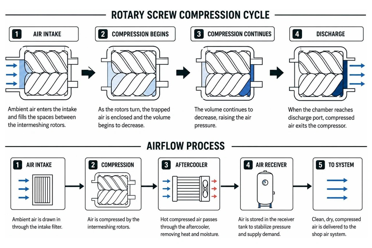
Modern rotary screw units typically utilize totally enclosed fan-cooled (TEFC) drive motors and integrated air-cooled aftercoolers. Light industrial models (3 to 30 HP) deliver between 10 and 125 CFM of airflow, making them the standard choice for multi-bay operations. By integrating sound-attenuated enclosures, these packages operate around 65 to 70 dBA, allowing shops to place the compressor directly on the service floor without exceeding workplace noise thresholds. For complete design guidelines, consult our detailed resource on Air Compressor Installation for Automotive Shop.
Reciprocating Piston Shop Air Compressors
Reciprocating piston compressors utilize a crankshaft-driven connecting rod and piston inside a cast iron cylinder. In commercial settings, two-stage models compress intake air to an intermediate pressure in the first cylinder, route it through a finned intercooler tube, and then compress it to final pressure (typically 175 PSI) in the second cylinder.
Piston units are cost-effective for shops with intermittent pneumatic cycles. However, standard piston pumps are limited to a 60% to 70% duty cycle. If a technician team pushes a reciprocating unit beyond its thermal limits, friction builds, oil carryover escalates into the air lines, and valve failure follows. When sourcing cast iron reciprocating machinery, exploring vetted Michigan Air Compressor Manufacturers helps ensure you invest in heavy-duty commercial blocks rather than light consumer-grade hardware.
Rotary Vane and Oil-Free Scroll Units
Rotary vane compressors utilize a slotted rotor with sliding blades that sweep against an eccentric stator ring. As the rotor turns, centrifugal force extends the vanes, creating compression pockets. These units are known for mechanical simplicity, low vibration, and operational lifespans that often exceed 100,000 running hours in commercial environments.
Oil-free scroll compressors operate using two interleaving scrolls—one stationary and one orbiting—to compress intake air without any oil lubrication inside the compression chamber. Certified to ISO 8573-1 Class Zero standards, scroll compressors deliver 100% oil-free air. They are utilized where zero hydrocarbon contamination is strictly mandatory, such as dedicated automotive refinishing and high-end paint spray booths.
Sizing Compressor Capacity: CFM, PSI, and Horsepower Calculations
Sizing a commercial compressed air system requires matching volume flow (Cubic Feet per Minute, CFM) at specific operating pressures (Pounds per Square Inch, PSI) to prevent tool starvation during peak bay hours. For an in-depth operational breakdown, review our Compressed Air Systems Ultimate Guide 2026.
Evaluating Total CFM and Operating Pressure Requirements
Most commercial pneumatic equipment operates at 90 to 100 PSI, but the central system must produce higher line pressure (125 to 175 PSI) to overcome friction drops across piping networks, filtration modules, and regulators.
| Automotive Shop Equipment | Average Air Consumption (CFM @ 90 PSI) | Typical Bay Usage Factor |
|---|---|---|
| 1/2-Inch Impact Wrench | 4 – 6 CFM | 0.20 – 0.30 (Intermittent) |
| 3/4-Inch / 1-Inch Heavy Impact Wrench | 10 – 14 CFM | 0.20 – 0.30 (Intermittent) |
| Pneumatic Die Grinder / Cut-Off Tool | 8 – 12 CFM | 0.50 – 0.60 (Moderate-Continuous) |
| Dual-Action (DA) Orbital Sander | 10 – 16 CFM | 0.60 – 0.80 (Heavy-Continuous) |
| HVLP Paint Spray Gun | 12 – 18 CFM | 0.70 – 0.90 (Sustained Continuous) |
| Tire Changer / Bead Seating Blast | 3 – 5 CFM | 0.15 (Intermittent) |
| Automotive Fluid Evacuator / Pump | 4 – 8 CFM | 0.30 (Intermittent) |
To size a 6-bay mechanical shop running three 1/2-inch impact wrenches, one pneumatic die grinder, and one tire changer concurrently:
- Multiply each tool's base CFM by its usage factor.
- Sum the adjusted figures. For the three impact wrenches, multiply 5 CFM by 0.25 for each tool, which equals 3.75 CFM. For the die grinder, multiply 10 CFM by 0.50, which equals 5.0 CFM. For the tire changer, multiply 4 CFM by 0.15, which equals 0.6 CFM. Adding these together gives 9.35 CFM.
- Add a 25% system buffer for future service bay additions or minor distribution line leakage. Multiply 9.35 CFM by 1.25, which equals 11.7 CFM.
Motor Horsepower, Duty Cycle, and Power Sizing
A commercial compressor generally delivers approximately 3.5 to 4.5 CFM per motor horsepower at 100 to 125 PSI.
- A 5 HP compressor generates roughly 16 to 18 CFM.
- A 7.5 HP compressor delivers roughly 25 to 28 CFM.
- A 10 HP unit provides roughly 35 to 40 CFM.
- A 15 HP system delivers roughly 50 to 60 CFM.
If your calculated shop demand is 28 CFM continuous, a 7.5 HP reciprocating piston compressor running near max output will overheat because its duty cycle is limited to 60–70%. In this scenario, you must either upgrade to a 10 HP piston unit to allow cooldown cycling or install a 7.5 HP rotary screw compressor built for continuous runtime.
Receiver Tank Configurations and Air Storage Dynamics
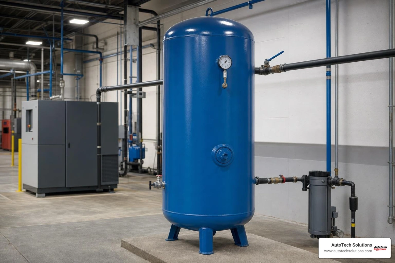
Receiver tanks serve three critical functions: storing compressed air for sudden high-volume demands, dampening pressure pulsations from reciprocating pumps, and allowing moisture to cool and drop out of suspension before entering the shop lines.
Vertical vs. Horizontal Commercial Air Receivers
Vertical receiver tanks have a compact base, making them ideal for modern service departments where floor space is prioritized for vehicle lifts and workbenches. Vertical configurations also facilitate clean condensate drainage, as moisture pools naturally at the bottom-center drain port.
Horizontal receiver tanks are commonly used for integrated compressor-on-tank assemblies where the motor, pump, and electrical enclosures mount directly onto a top saddle plate. These units simplify installation in equipment rooms with lower ceiling heights.
Sizing Gallon Capacity to Mitigate Pressure Drop
As a rule of thumb, commercial installations require 3 to 5 gallons of receiver tank capacity for every CFM of compressor output.
- 80-Gallon Receivers: Suited for 5 to 7.5 HP systems (15–28 CFM) handling light-to-medium automotive service bays.
- 120-Gallon Receivers: Standard for 10 to 15 HP compressors (35–60 CFM) supporting multi-bay fleets, heavy tire changers, and sustained sanding.
- 240-Gallon+ Receivers: Engineered for high-volume commercial centers with fluctuating surge loads to prevent rapid pump cycling and line drawdown.
Electrical Specifications, Duty Ratings, and Drive Types
Improper electrical supply leads to tripped thermal overloads, dropped phases, and premature motor burnouts. Ensuring your facility's panel can supply the necessary voltage and starting current is a prerequisite for any major equipment upgrade. For troubleshooting motor issues, see our guide on Air Compressor Motor Repair.
Single-Phase vs. Three-Phase Power Infrastructure
- Single-Phase (208/230V, 1-Phase): Common in smaller standalone shops. Single-phase motors draw higher running and inrush amperages, limiting single-motor compressor sizes to 7.5 or 10 HP.
- Three-Phase (208/230/460V, 3-Phase): The commercial standard for mid-to-large facilities. Three-phase power balances electrical current across three alternating legs, reducing running amperage, allowing smaller wire gauges, and supporting motors from 10 HP to over 100 HP.
Commercial installations should always use dedicated circuits, industrial-grade disconnect boxes, and properly matched magnetic starters with thermal overload protection to prevent low-voltage phase-loss damage.
Fixed Speed vs. Variable Speed Drive (VSD) Systems
Fixed-speed compressors operate at a constant RPM. When the shop reaches cut-out pressure, the unit either unloads (idling while consuming up to 30% of full-load electricity) or shuts off completely via start-stop control.
Variable Speed Drive (VSD) compressors use an intelligent inverter to adjust motor speed to match real-time shop demand. If your shop is only using 40% of the compressor's capacity, the VSD slows the motor accordingly, maintaining a steady target line pressure within ±1.5 PSI.
VSD compressors provide turndown ranges between 20% and 100% capacity, eliminating the high amperage spikes of across-the-line motor starts and reducing utility costs in facilities with varying daily shift volumes.
Essential Air Treatment and Distribution Accessories
Generating compressed air is only half the battle; conditioning and delivering that air cleanly to the bay tools is what prevents equipment failures and rework.
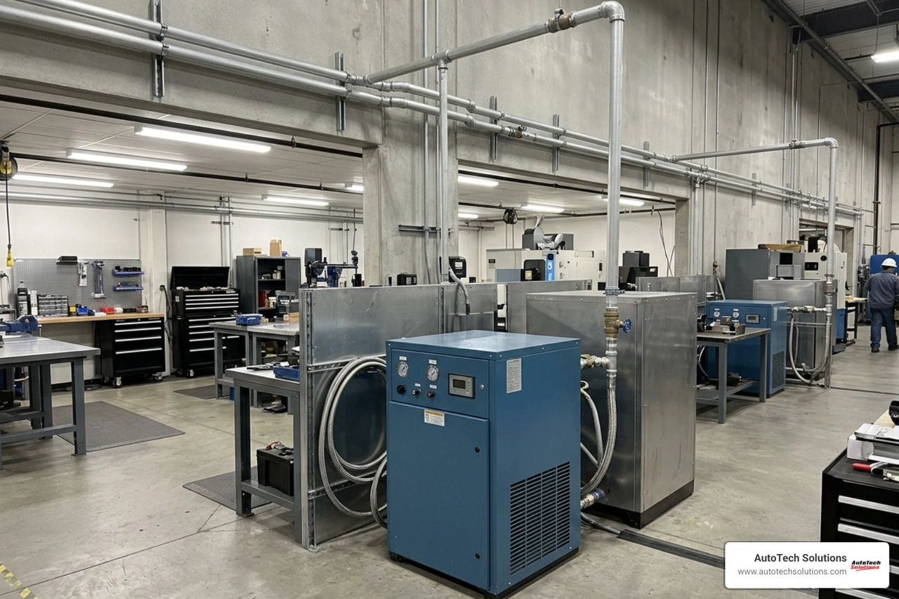
Refrigerated Dryers and Coalescing Filtration
Atmospheric air entering the compressor contains moisture, particulate matter, and ambient oil vapors. When compressed to 150 PSI, water vapor condenses inside downstream pipe networks.
- Refrigerated Air Dryers: Lower the compressed air temperature to approximately 38°F (+3°C), condensing moisture vapor into liquid water so it can be automatically purged.
- Coalescing & Particulate Filters: Positioned upstream and downstream of the dryer, these filters remove solid particulates down to 0.01 microns and separate sub-micron oil aerosols down to 0.01 mg/m³.
- Oil-Water Separators: Collect all drained compressor condensate and filter out lubricants before the water is legally discharged into municipal drain networks.
Distribution Piping and Condensate Management
Traditional black iron or galvanized pipe rusts internally over time, dropping scale into expensive pneumatic tools and creating friction-induced pressure drop. Modern commercial facilities utilize smooth-bore modular aluminum piping systems that eliminate corrosion, minimize flow friction, and provide push-to-connect installation flexibility.
Installing a properly balanced Compressed Air Ring Main allows air to circulate bidirectionally around the facility perimeter, equalizing pressure drops during peak tool usage. Combine this with electronic zero-loss condensate drains and drop-leg moisture traps at every technician station to keep your supply dry and reliable.
Frequently Asked Questions About Shop Air Compressors
How do I calculate total CFM requirements for a multi-bay commercial automotive shop?
Calculate the CFM requirements for each pneumatic tool, multiply each tool by its realistic bay usage factor (typically 0.20 to 0.35 for impact tools; 0.70 to 0.90 for spray equipment), sum these values for all concurrently operating bays, and add a 25% safety buffer for future expansion and line losses.
When should a commercial facility choose a rotary screw over a reciprocating piston compressor?
A facility should transition to a rotary screw compressor when total pneumatic demand requires 100% continuous duty cycles, when multiple technicians operate continuous-draw tools (such as sanders or spray booths) simultaneously, or when equipment must be installed near service bays where low decibel levels (under 70 dBA) are required.
What maintenance schedule is necessary to prevent commercial compressor downtime?
Routinely inspect intake filters, check oil sight-glasses weekly, and drain manual water traps daily. Replace full synthetic compressor lubricants, spin-on oil filters, air intake elements, and separator cartridges every 2,000 to 4,000 operating hours (or annually). Review our complete Air Compressor Preventative Maintenance Guide for comprehensive service checkpoints.
Conclusion
A properly engineered compressed air system is the operational backbone of any productive automotive service department or commercial collision shop. By matching your equipment choices—whether high-efficiency rotary screws, heavy-duty two-stage pistons, or responsive VSD systems—with correctly sized receiver storage and refrigerated air treatment, you protect your pneumatic equipment and eliminate costly shop downtime.
At AutoTech Solutions, our factory-trained technicians provide comprehensive support across Charlotte, NC, Raleigh, NC, Wade, NC, and Novi, MI. From initial bay sizing, professional car lift installation, and modular aluminum piping setup to scheduled preventative maintenance and fast emergency service, we keep your shop running at full capacity. Contact us today to schedule your facility's system consultation and explore our professional equipment service and preventative maintenance programs.