How to Execute Commercial Car Lift Hydraulic Cylinder Repair
To perform a professional car lift hydraulic cylinder repair, follow this five-step overhaul workflow:
- Isolate and depressurize: Lower the lift carriage onto mechanical safety locks, apply lockout/tagout (LOTO) procedures, and relieve all residual hydraulic line pressure before disconnecting hoses into a clean catch basin.
- Extract and disassemble: Unpin the cylinder from the lift column, clamp the barrel into a soft-jaw bench vise, remove the gland retaining ring or gland nut using a dedicated pin spanner wrench, and carefully pull the rod assembly straight out.
- Inspect tolerances: Measure the internal bore and chrome rod for scoring, corrosion, runout, or ovality beyond standard service limits (typically ≤0.05 mm scoring depth).
- Reseal the assembly: Strip old seals with non-marring brass picks and install new, lubricated polyurethane U-cups, backup rings, and wiper seals in the correct directional pressure orientation.
- Reassemble, bleed, and test: Re-torque all components to OEM specifications, reinstall the cylinder, refill the reservoir with fresh ISO VG 32 hydraulic fluid, cycle the lift to purge trapped air, and run a 1.5× working pressure static hold test.
In a busy commercial service facility, a failing hydraulic cylinder stalls productivity and threatens bay safety. Whether dealing with external gland fluid weeping or internal piston bypass causing uncommanded carriage settling, prompt mechanical intervention restores hydraulic integrity and prevents catastrophic structural failure.
As the AutoTech Solutions Staff, our goal is to help your service department maintain equipment reliability, protect technician safety, and eliminate costly bay downtime.
Diagnosing Commercial Auto Lift Hydraulic Cylinder Failures
Commercial automotive lifts operate under demanding conditions, handling thousands of lift cycles each year at system pressures typically reaching 2,500 to 3,000 PSI. When hydraulic components begin to wear, the symptoms range from subtle fluid weeping around the gland collar to rapid carriage settling under load. Identifying hydraulic anomalies early eliminates common causes of automotive lift downtime and ensures technician safety during daily shop operations.
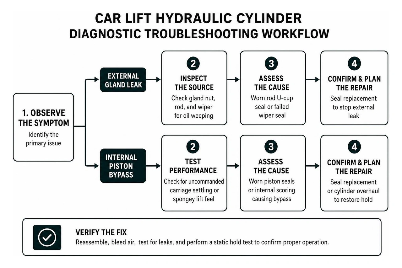
External Gland Leaks vs Internal Piston Bypass
Diagnosing a failing hydraulic cylinder begins by isolating whether the issue stems from an external seal breach or an internal pressure bypass:
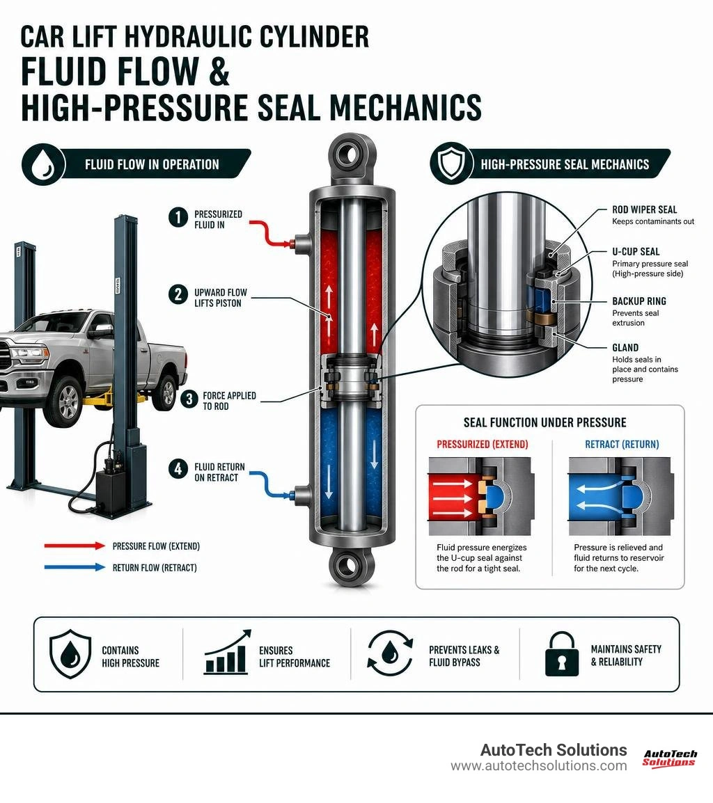
- External Gland Leaks: This failure presents as visible oil film, active dripping, or pooling around the cylinder gland nut and down the chrome piston rod. It occurs when the primary rod U-cup seal degrades from friction, high cycles, or contamination. Once the rod wiper fails, ambient shop dirt and particulate matter enter the gland, accelerating seal breakdown and leading to noticeable fluid loss on the bay floor.
- Internal Piston Bypass: This condition occurs when high-pressure hydraulic fluid slips past worn piston seals into the unpressurized low-pressure or return side of the cylinder. The primary symptom is uncommanded carriage settling (drift) while under load, even when no external fluid leaks are visible. In dual-cylinder direct-drive or chain-over systems, internal bypass causes side-to-side carriage unevenness during elevation.
To confirm an internal bypass versus a faulty power unit lowering valve or holding check valve, lower the lift onto its mechanical locks, isolate the hydraulic lines, and perform a port flow bypass test. If fluid flows out of the opposite cylinder port while pressurized, the internal piston seals have failed.
Structural Cylinder Inspection and Tolerance Verification
Before ordering replacement seals, commercial shop maintenance technicians must inspect the structural steel components to confirm the cylinder can be safely overhauled. Re-sealing an out-of-round barrel or a bent rod guarantees immediate seal failure:
- Piston Rod Runout: Measure rod straightness using a dial indicator while rotating the rod on V-blocks. Acceptable straightness runout must not exceed 0.5 mm per meter. Any rod exceeding this tolerance will exert uneven lateral loads on the gland bushing and blow out new seals.
- Surface Finish and Chrome Condition: Inspect the hard chrome plating for micro-grooving, flaking, or rust pitting. The optimal rod surface finish is Ra 0.1–0.2 µm. If deep gouges exceed 0.05 mm or surface roughness exceeds Ra 0.4 µm, re-chroming or rod replacement is mandatory.
- Barrel Bore Ovality and Scoring: Use an internal three-point bore micrometer to measure the inner cylinder tube across multiple depths. Barrel ovality must remain below 0.1 mm. Longitudinal scratches deeper than 0.05 mm cannot be cleaned up through light cross-hatch honing and require barrel replacement.
Tooling and Safety Protocols for Car Lift Hydraulic Cylinder Repair
Servicing high-pressure commercial lift cylinders requires specialized shop equipment and strict adherence to industrial safety standards. Hydraulic circuits store massive mechanical energy; improper handling can cause catastrophic physical injury from pressurized fluid injection or uncontrolled carriage descent.
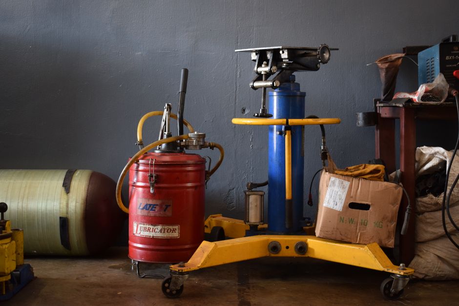
Commercial Shop Lockout/Tagout and Mechanical Support
Before turning a single wrench, shop technicians must execute a complete lockout/tagout (LOTO) procedure on the automotive lift power unit:
- Engage Mechanical Safety Locks: Lower the lift carriages firmly onto the nearest mechanical safety lock latches. Never attempt to disconnect or service hydraulic cylinders while the carriages are supported solely by hydraulic oil column pressure.
- Depressurize the Hydraulic System: Disconnect the electrical power disconnect switch at the lift console and tag the breaker panel. Manually actuate the lowering control valve lever for 15 to 20 seconds to discharge all residual hydraulic line pressure back into the fluid reservoir.
- ANSI/ALI Standard Compliance: Ensure all maintenance operations adhere strictly to ANSI/ALI ALCTV (Standard for Automotive Lifts - Safety Requirements for Construction, Testing, and Validation) guidelines, verifying that all load-bearing mechanical safety locks are fully seated and operational.
Fluid Containment and Workspace Cleanliness Standards
Particulate contamination is the leading cause of premature hydraulic seal failure. Grit as small as 5 to 10 microns acts like liquid sandpaper against dynamic polyurethane seals:
- Containment Basins: Position heavy-duty fluid drain basins beneath line connections and cylinder ports before loosening JIC or ORB hydraulic fittings. Plug open hoses and ports immediately using clean steel or plastic threaded caps.
- Lint-Free Cleaning: Prohibit the use of standard fiber-shedding shop rags. Wipe all components exclusively with industrial lint-free wipes and clean, non-chlorinated solvent.
- ISO 4406 Oil Cleanliness Standards: Ensure shop maintenance practices prevent fluid degradation. Maintaining hydraulic cleanliness to ISO 4406 levels of 18/16/13 protects against premature valve spool scoring and internal cylinder wear as part of ongoing car lift maintenance.
- Non-Marring Service Tools: Use dedicated brass or polymer seal picks, adjustable pin spanner wrenches, and soft-jaw aluminum vise inserts. Striking a gland nut with a pipe wrench or prying seals with hardened steel screwdrivers creates burrs that will slice new seals upon reassembly.
Technical Disassembly and Precision Component Inspection Procedures
Car lift hydraulic cylinders in commercial service typically feature either welded-gland or internal wire-ring retention configurations. Follow precise manufacturer teardown instructions, referencing established technical hydraulic cylinder service guidelines, to ensure zero damage to precision-machined internal surfaces.
Technical Teardown for Car Lift Hydraulic Cylinder Repair
Follow these structured mechanical steps to dismantle the cylinder assembly:
- Mounting Extraction: Remove the top and bottom clevis pins, retaining snap rings, or master link plates securing the cylinder inside the lift column. Hoist the cylinder clear of the column structure and mount the barrel base securely in a soft-jaw bench vise.
- Gland Release: For round-wire retaining ring cylinders, tap the guide bushing approximately 1/4 inch downward into the barrel to expose the internal wire snap ring. Extract the ring using a specialized hook tool. For threaded gland cylinders, engage a heavy-duty adjustable pin spanner wrench with the gland face holes and rotate counter-clockwise.
- Rod Extraction: Slowly draw the chrome piston rod assembly straight out of the cylinder barrel. Keep the rod perfectly centered along the axial bore line to avoid gouging the polished internal barrel wall with the piston edges.
- Thread Protection and Piston Removal: Wrap the exposed threads of the rod end with vinyl thread-masking tape before sliding off the gland assembly. Unbolt the primary piston retention nut using a calibrated impact socket or torque wrench while holding the piston flats securely. Slide the piston and rod gland off the shaft.
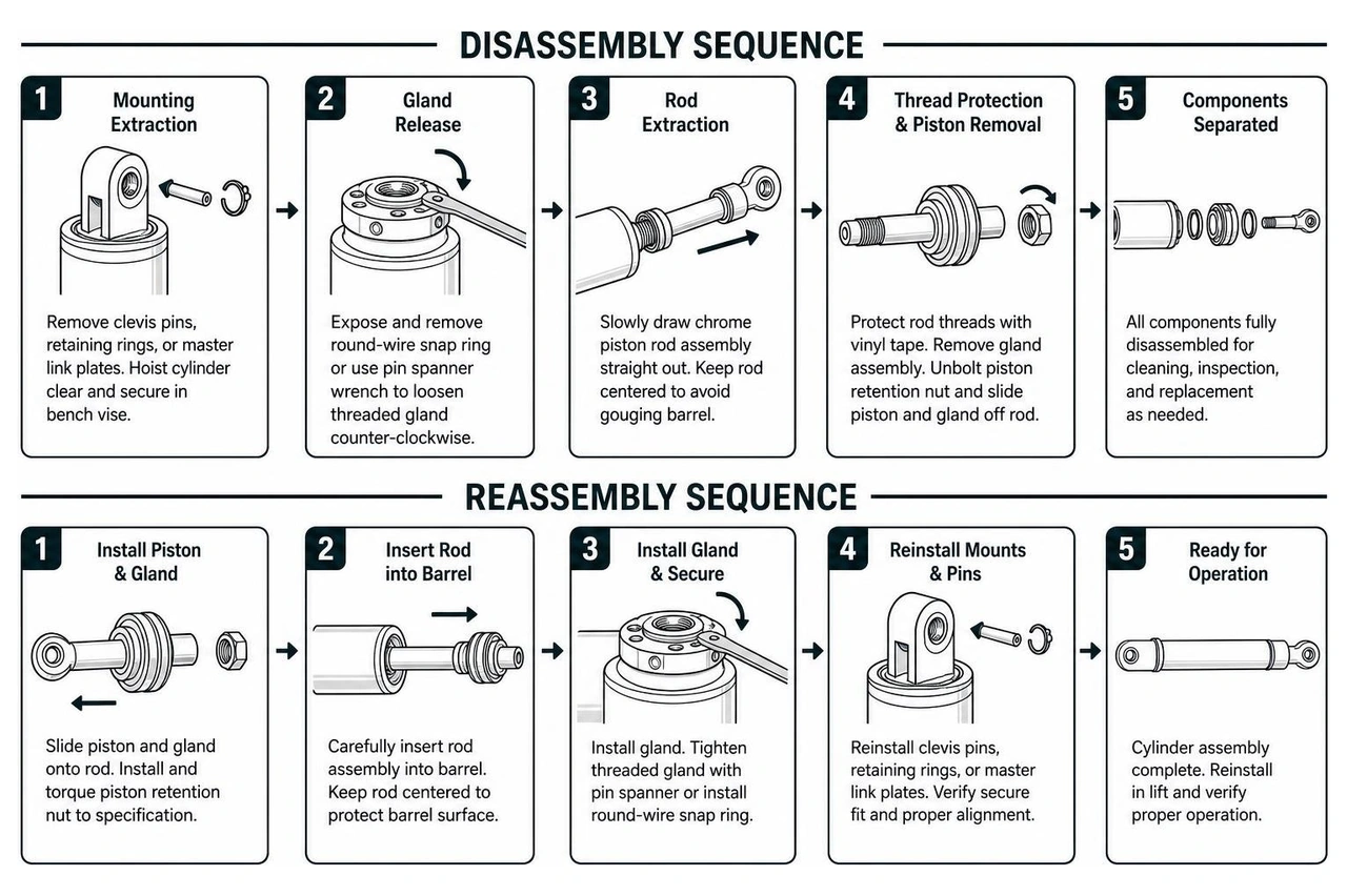
Assessing Barrels, Rods, and Mountings for Wear
With all components disassembled and washed in clean solvent, conduct a comprehensive wear assessment:
- Barrel Honing Procedures: If light surface oxidation or superficial scuffing is present (under 0.02 mm depth), hone the internal barrel using a flex-hone or rigid 3-stone cylinder hone (180–400 grit) lubricated with light honing oil. Maintain a 30° to 45° cross-hatch pattern. Flush the barrel completely with clean solvent afterward to remove all abrasive silicon carbide residue.
- Piston and Guide Bushing Fit: Check the inner diameter of the bronze or ductile iron rod guide bushing. If excessive play or egg-shaped wear is detected, replace the bushing to prevent rod deflection under asymmetric lifting loads during two post lift repair.
- Mounting Clevis and Pin Inspection: Inspect upper and lower mountings, link plates, and cross-pins for elongation, micro-cracks, or fretting wear. Worn mounting pins cause side-loading forces on the cylinder during carriage travel, drastically shortening seal lifespan.
Seal Replacement, Reassembly, and System Commissioning
Installing hydraulic seals requires absolute precision regarding elastomer choice, dynamic lip orientation, and correct torque application.
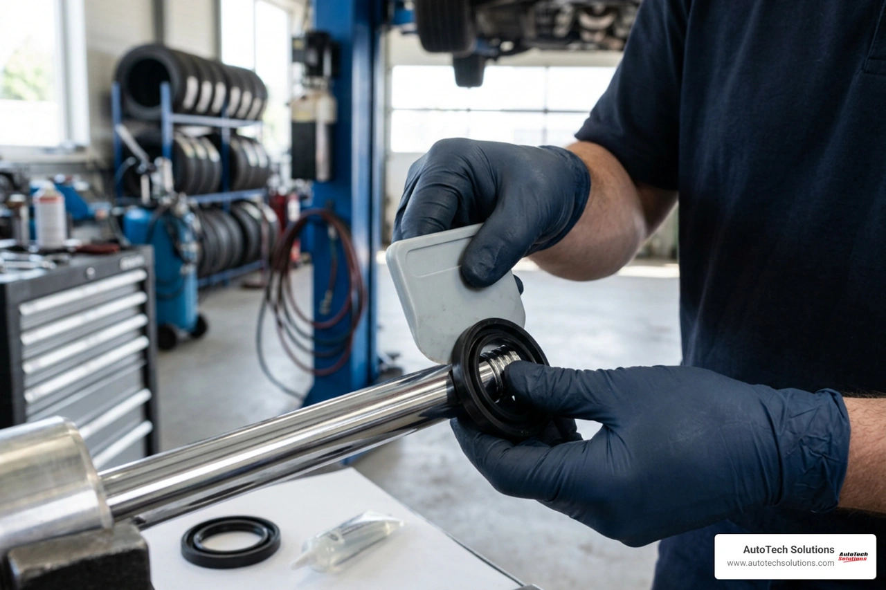
Seal Sizing and Seating in Car Lift Hydraulic Cylinder Repair
When replacing internal components, always cross-reference lift manufacturer part numbers or measure internal seal gland grooves rather than worn, stretched seals:
- Material Compatibility: Commercial automotive lifts require high-grade 90–95 Shore A polyurethane U-cup rod seals, dynamic NBR or PTFE piston seals with elastomeric energizers, and Viton or nitrile O-rings paired with hard Delrin anti-extrusion backup rings.
- Thermal Conditioning: To install stiff polyurethane rod seals without stretching or tearing them, soak the new seals in clean, warm hydraulic oil heated to approximately 140°F (60°C) for five minutes. This softens the elastomer, allowing flexible installation without folding sharp creases into the dynamic sealing lips.
- Correct Lip Direction: Always install U-cup and pressure seals with the open sealing lips facing toward the internal high-pressure fluid side of the cylinder. Install the outer rod wiper seal with the scraping lip facing outward to clear road dirt, shop dust, and metal shavings on cylinder retraction, following standard industrial cylinder rebuild procedures.
- Backup Ring Placement: When installing high-pressure dynamic O-rings, always position the hard backup ring on the downstream (low-pressure) side of the groove to prevent elastomer extrusion under 3,000 PSI operating spikes.
Reassembly Torquing, Fluid Replenishment, and Air Bleeding
Reassemble the cylinder on a pristine workbench using generous amounts of clean hydraulic oil on all dynamic components:
- Torque Application: Slide the gland bushing and piston back onto the masked rod. Apply high-strength thread locker to the piston retention fastener and torque to factory specifications. Piston nuts for standard commercial lifts (2-inch to 3.5-inch bores) typically require 150 to 250 ft-lbs (200–340 N·m) of torque.
- Re-insertion into Barrel: Lubricate the piston seals and barrel entry chamfer. Guide the piston assembly straight into the barrel using a tapered seal sleeve or gentle compression to avoid nicking seal lips on barrel threads. Reinstall and torque the gland nut or secure the internal wire snap ring.
- Fluid Replenishment: Remount the cylinder in the lift column, re-pin the mountings, and reconnect all hydraulic lines without twisting the hoses. Refill the power unit reservoir with clean, high-grade ISO Grade 32 (or ISO Grade 46 depending on ambient operating environment) anti-wear hydraulic oil containing anti-foaming and anti-oxidation additives.
- Air Bleeding Procedure: Trapped air in hydraulic lines is compressible, creating spongy carriage elevation, bouncing, and cavitation growl. Loosen the cylinder bleeder screw (if equipped) at the top of the stroke or cycle the lift carriages up and down through 4 to 6 complete, unladen strokes. Allow a 5-minute rest period between cycles to let aerated foam dissipate in the fluid reservoir, ensuring smooth performance across all hydraulic lift cylinder repair tasks.
- Equalization Cable Balancing: Re-check and calibrate the mechanical synchronization cables on dual-column lifts to ensure both carriages contact their safety locks in perfect unison.
Post-Rebuild Proof Testing and Pressure Verification
Before returning an automotive lift to active service in your shop, execute a rigorous three-stage proof testing protocol:
- Low-Pressure Leak Inspection: Cycle the lift carriages at 150–300 PSI (10–20 bar) unladen. Inspect the rod gland collar and hose unions for immediate fluid weeping.
- Full-Pressure Static Hold Test: Place a test load on the lift, raise the carriages clear of the mechanical locks, and hold the load under hydraulic pressure at 1.5× working pressure for 3 minutes.
- Drift Measurement: Measure vertical cylinder position over a 15-minute static hold. Holding drift must not exceed 1% of total stroke length. Check that velocity fuses, flow restrictors, and mechanical safety lock mechanisms drop and engage cleanly at each locking increment.
Commercial Rebuild vs. Replacement Analysis for Service Bays
Deciding whether to overhaul an existing hydraulic cylinder with a seal kit or install a complete OEM/aftermarket replacement assembly depends on structural condition, component cost, and bay downtime economics.
| Parameter | Professional Seal Kit Overhaul | Complete Cylinder Replacement |
|---|---|---|
| Direct Parts Cost | $75 – $175 (Seal Kit) | $630 – $1,700+ (New Assembly) |
| Specialized Labor Time | 2.0 – 3.5 Hours (Teardown, Hone, Seal) | 0.75 – 1.5 Hours (R&R Complete Assembly) |
| Total Repair Cost | $250 – $500 | $750 – $2,000+ |
| Bore Scoring Tolerance | Must be ≤0.05 mm (Honeable) | Required if scoring >0.05 mm or bore bulged |
| Rod Straightness Limit | Must be ≤0.5 mm/m runout | Required if bent, cracked, or deeply gouged |
| Bay Downtime Impact | Moderate (Requires bench overhaul) | Minimal (Rapid swap-out) |
| Typical Component Life | 5 – 8 Years (Standard commercial use) | 10+ Years (Brand new OEM unit) |
If the cylinder barrel exhibits internal scoring exceeding 0.05 mm, barrel ovality, or deep chrome spalling on the rod, replacing the complete cylinder assembly is the only safe and cost-effective path. Evaluating these factors helps facility managers achieve rapid downtime reduction lift repair while maintaining compliance and safety.
Frequently Asked Questions About Commercial Lift Cylinders
How do commercial technicians differentiate between external rod seal leaks and internal piston bypass?
External leaks are identified by fluid weeping past the gland nut, wet oil films on the chrome rod, or pooling on the bay floor, signaling worn rod U-cups and wiper seals. Internal bypass occurs when pressurized fluid slips past the internal piston seals to the unpressurized side, resulting in uncommanded carriage settling (drift) under load or side-to-side lifting unevenness without any external oil leakage.
What hydraulic fluid specification is mandatory for commercial car lift hydraulic cylinders?
Commercial automotive lift manufacturers specify premium ISO Grade 32 or ISO Grade 46 anti-wear (AW) hydraulic oil. These fluids contain dedicated anti-foaming, anti-wear, and anti-oxidation additives that prevent pump cavitation, maintain viscosity stability across wide shop temperature swings, and protect internal polyurethane seals and chrome rods from premature degradation.
When does cylinder rod or bore damage dictate full component replacement over resealing?
A cylinder must be replaced rather than resealed if the chrome rod straightness runout exceeds 0.5 mm per meter, if longitudinal barrel scratches exceed 0.05 mm in depth, if the barrel exhibits bore ovality beyond 0.1 mm, or if the rod has deep corrosion pitting and chrome flaking that cannot be polished out without falling below dimensional tolerances.
Conclusion
Maintaining hydraulic cylinder integrity is essential for commercial shop safety, bay efficiency, and uninterrupted service revenue. Implementing routine inspections, verifying hydraulic oil cleanliness, and addressing gland weeping immediately prevents severe structural damage and keeps your automotive service bays running at maximum capacity.
When commercial repair demands exceed internal shop resources, turn to certified specialists. AutoTech Solutions provides light, heavy, and collision shops across our locations in Charlotte, NC, Raleigh, NC, Wade, NC, and Novi, MI with rapid emergency repairs, factory-certified equipment maintenance, and turnkey lift installations. To schedule an on-site equipment inspection or restore your shop's lifting infrastructure, reach out to our team for expert commercial lift service and equipment support.